
Operator's Manual
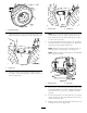
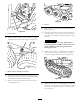
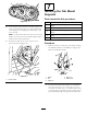
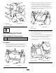
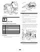
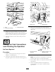
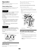
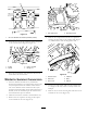
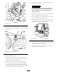

Figure63
1.Frontcover
9
MountingtheCab
Partsneededforthisprocedure:
4
Rubbercabmount(suppliedwithcabmodel30371)
4
Bolt(1/2x3inches)(suppliedwithcabmodel30371)
4
Washer-Steel(1/2x2–1/2inches)(suppliedwithcab
model30371)
4
Washer-rubber(1/2x2–1/2inches)(suppliedwithcab
model30371)
4
Nut(1/2inch)(suppliedwithcabmodel30371)
2
Cornermat(suppliedwithcabmodel30371)
1
PowerPointShield
Procedure
1.Removetheclipsecuringthedoorclosersockettothe
doorbracketball(
Figure64).
Figure64
1.Cabdoorbracket3.Clip
2.Doorcloser
Note:Thecabdoorsandwindowsmayberemoved
toeaseinstallation,decreasetheliftingweightandto
preventpossibledamage.
2.Removethefastenerssecuringthecabtotheshipping
pallet.
3.Insertarubbercabmountatthefrontandrear
mountinglocations(
Figure65).
4.Usingasuitableoverheadhoist,carefullyliftthe
cabintopositiononthemachine.Usecautionnot
todamagecabroof,controls,hosesorelectrical
connectors.
5.Ateachmountingpoint,securethecabtothemachine
withabolt(1/2x3inches),steelwasher(1/2x2–1/2
inches),rubberwasher(1/2x2–1/2inches)andnut
(1/2inch)(Figure65).Tightentheboltsuntilthe
rubbermountsarecompressedtoathicknessof2.2
cm(7/8inch).
Figure65
1.Rubbermount
2.0.875inch(2.2cm)
6.Removetheboltsecuringthepowerpointassemblyto
therightfrontcornerofthecabframe(Figure66).
25