
Operator's Manual
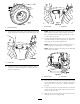
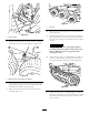
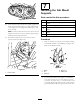
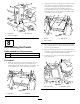
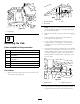
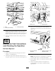
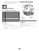
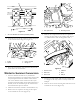
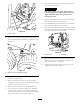

Figure76
1.Accesscovers
7.Removethe1/2inchlocknutandatwasherfromthe
leftandrightbogiepivotweldmenttounlatchthepivot
(Figure77).
Figure77
1.Washer&nutonthebogiepivotstud
8.Positionasuitableoorjackunderthecenterofthe
frontliftarmpivottube.
9.Raisetheoorjackuntiltherearofthemachineis
supportedonthejackstandsandthecentertireswings
backandnearlycontactsthereartire.
10.Removethecenterandrearwheelsfromeachside.
11.Lowertheoorjackuntilthebogiepivotweldment
movesenoughsothatthe1/2inchatwasherand
locknutcanbeinstalledonthestudandthreadednger
tightonbothsidesofthemachine(
Figure77).
12.Raisetheoorjackhighenoughsothatthetrackcan
beslidoffofthefronttire.
CAUTION
Thetrackguideshavemanypinchpoints.
Carefullygrasptherubbertrackontheouter
edgesoutboardofthesteelguideswhen
movingthetrack.
13.Repeattheprocedureontheothersideofthemachine.
Movethetracksawayfromthemachine.
14.Placeanadditionaljackstandunderfrontofmachine.
Placeadrainpanunderthecontrolvalve.
15.Disconnectthetankhosefromthecontrolvalvehard
line(Figure78).Capthehoseandtting.Pullthetank
hosebacktowardtherearoftheframe.
G009488
1
2
Figure78
1.Pressurehose2.Tankhose
16.Disconnectthepressurehosefromthecontrolvalve
(Figure78).Capthehoseandtting.Pullthehose
backtowardtherearoftheframe.
17.Unplugthecabharnessconnector(Figure79)and
installthecapontotheconnector.
30