Form No. 3360-906 Rev A Polar Trac Kit Groundsmaster 7200/7210 Series Mowers Model No. 30370—Serial No. 280000001 and Up Model No. 30371 Register at www.Toro.com.
injury or death if you do not follow the recommended precautions. Warning CALIFORNIA Proposition 65 Warning Diesel engine exhaust and some of its constituents are known to the State of California to cause cancer, birth defects, and other reproductive harm. Figure 2 1. Safety alert symbol This manual uses 2 other words to highlight information. Important calls attention to special mechanical information and Note emphasizes general information worthy of special attention.
Preparation Safety • While operating, always wear substantial footwear and long trousers. Do not operate the equipment when barefoot or wearing open sandals. • Thoroughly inspect the area where the equipment is to be used and remove all objects which may be thrown by the machine. • Warning- Fuel is highly flammable. – Store fuel in containers specifically designed for this purpose. – Refuel outdoors only and do not smoke while refueling. – Add fuel before starting the engine.
• When using any attachments, never direct discharge of material toward bystanders nor allow anyone near the machine while in operation. Some attachments, such as a snowthrower, are capable of amputating hands and feet and throwing objects – stay alert for humps and hollows and other hidden hazards; • Do not operate near drop-offs, ditches, steep banks or water. Tracks dropping over edges can cause roll overs, which may result in serious injury, death or drowning.
Safety and Instructional Decals Safety decals and instructions are easily visible to the operator and are located near any area of potential danger. Replace any decal that is damaged or lost. The following instructional decal is applied to components supplied with this kit and is used in the conversion process. 112-6312 1. Read the Operator’s Manual.
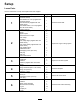
Setup Loose Parts Use the chart below to verify that all parts have been shipped. Procedure 1 2 3 4 5 6 Description Qty.
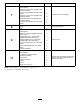
Procedure 7 8 9 11 Description Use Qty.
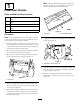
Note: The heat shield material must be affixed so that the rear panel can be reinstalled to the frame without pinching the heat shield material. 1 Install Heat Shields Parts needed for this procedure: 1 Heat shield-rear panel (supplied with cab model 30371) 1 Heat shield-front cover (supplied with cab model 30371) 1 Heat shield-seat (supplied with cab model 30371) 1 Heat shield-seat 2 x 10 inch (supplied with cab model 30371) 3 Rubber grommet Figure 4 1.
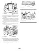
Figure 8 1. Front cover 2. Heat shield 14. Install rubber grommets into the 3 holes in the rear frame mount as shown in (Figure 9). Figure 6 1. Heat shield 2. Heat shield 2 x 10 inch piece 9. Insert the seat wire harness through the slit in the heat shield. 10. Remove the backing and affix the 2 x 10 inch piece of self-adhesive heat shield between the seat latches on the bottom of the seat mount plate (Figure 6). Figure 9 1. Rubber grommets 11.
2. On the left rear corner of the cab assembly, locate the label on the hose marked “Pressure” (Figure 10). 2 3. Measure down 17 inches (43.1 cm) from where the hose exits the frame, mark the hose and cut the hose at this location (Figure 11).
Figure 14 1. Rear frame mount Figure 12 1. Return hose 2. Pressure hose 3. Hose clamps 4. Quick disconnect coupler 5. Nipple coupler 9. Install the bulkhead bracket to the left rear frame mount with 2 self-tapping screws (5/16 inch) (Figure 15). 6. Insert the barb end of a quick disconnect coupler into the return hose and secure with a hose clamp (Figure 12). 7. From the remaining piece of hose cut 2 lengths of hose, 55 inches (140 cm) and 22–1/2 inches (57 cm) (Figure 13). Discard any remaining hose.
Figure 18 Figure 16 1. Quick disconnect coupler 2. Dust plug 1. Radiator hose 2. Tee fitting 3. Nipple coupler 4. Dust cap 3. 52 inch long hose 15. Connect the 55 inch (140 cm) length of previously cut hose to the new tee fitting in the radiator hose (Figure 18 ). Secure the hose to the tee fitting with a hose clamp. Route the hose behind the radiator over flow tank, up the right side of the radiator, across the top of the radiator to the left side and under the air cleaner as shown in Figure 20.
Figure 20 1. 22–1/2 inch hose 2. 52 inch Hose 3. Cable tie Figure 22 16. Disconnect the wire and remove the thermo-switch from the left side of the engine thermostat housing (Figure 21). Discard the switch. 1. Engine thermostat housing 3. 22–1/2 inch (57 cm) long hose 4. Hose clamp 2. Hose adapter fitting 18. Connect the 22–1/2 inch (57 cm) length of hose to the engine thermostat housing adapter fitting (Figure 22). Secure the hose to the adapter fitting with a hose clamp.
20. Install the new dual contact switch to the right side of the engine thermostat housing (Figure 24). Figure 25 1. Rear frame mount 2. Grommet 2. Unlatch the control panel cover and lay it to the side (Figure 26). Figure 24 1. Dual contact switch 3. Harness connector 4. Connector cap 2. Wire from old left switch 21. Secure the wire, previously connected to the right side switch, to the male spade terminal. 22.
7. Insert the fusible link connector through the rubber boot on the positive battery cable. 8. Connect the fusible link to the positive battery post (Figure 29). 9. Connect the black wire to the negative battery post (Figure 29). Figure 27 1. Harness 2. Harness wire clips 3. Long cab wire (orange) 4. Cable tie 4. Inside the control panel, locate the pink wire with the connector enclosed in a plastic bubble (Figure 28).
5 Removing the Mower Deck Parts needed for this procedure: Figure 30 1. Rear bumper tube 2 Vertical tube support assembly 2 Clevis pin 2 Self-tapping screw (1/4 inch) 2 Hose plug 2. Floor jack Procedure 2. Install the skid plate (Figure 31) to the frame below the engine as follow: A. Mount the front of the skid plate to the skid mounting plate with 2 flange-head bolts (3/8 x 1-3/4 inches) and flange nuts (3/8 inch) (Figure 31). B.
Figure 35 1. Drive shaft 2. Gear box 3. Bolts 4. Roll pin 5. Remove the retaining ring securing the rear of the deck lift cylinder to the pivot pin (Figure 36). Figure 33 1. Deck frame 3. Clevis pin & self-tapping screw 2. Vertical tube support 3. Pivot open the floor plate (Figure 34) and secure with prop rod. Figure 36 1. Deck lift cylinder 2. Retaining ring 3. Screw 4. Cylinder pin 6. Remove the screw securing the front cylinder pivot pin to the mower frame (Figure 36).
Note: The floor jack can be raised or lowered to ease removal of the bolts. Lower the floor jack completely once the bolts are removed. Figure 39 Figure 37 1. 3 mounting bolts (3/4 inch) washers and nuts (Left side) 1. Deck lift cylinder 8. Disconnect the tank hose from the control valve (Figure 38). Install the cap from the winter kit valve into the control valve fitting and plug the hose with the plug supplied. Figure 40 1. Two mounting bolts (3/4 inch), washers and nuts (Right side) 12.
6 Installing the Winter Frame Assembly Parts needed for this procedure: 2 Hose cover 4 Cable tie 1 Winter frame assembly 6 Wheel and tire assembly 20 Lug nut 2 Coupler pin 2 Tracks Figure 42 1. Pump 2. Pressure hosed fitting (rotated 45 degrees) 4. Remove the two screws securing the floor plate cover to the floor and remove the plate (Figure 43). Procedure 1. Insert a 2 x 4 between the front bogie stop and the frame to tilt the winter frame toward the rear (Figure 41). Figure 43 1.
Figure 44 1. Drive shaft 2. Frame tube Figure 46 6. Route the hoses as follows: 1. Pressure hose 2. Tank hose 3. Hose cover • Route the pressure hose under the lift cylinder and between the cylinder mounting brackets to the valve (Figure 45). 4. Cable tie 5. Bolts 6. Roll pin 8. With the winter frame against the rear frame, raise the floor jack enough to remove the summer drive tires (Figure 47). Install the winter tires with 2 lug nuts per side.
1 2 G009488 Figure 50 1. Pressure hose Figure 48 2. Tank hose 1. Coupler pin 12. Raise the rear of the machine until 2 jack stands can be positioned under the rear tube at a height that supports the rear tires 1 to 3 inches (2.5 to 7.5 cm) off of the ground. 10. Adjust the floor jack as required to install the bolts (3/4 inch) on each side (Figure 49). Torque the bolts to 265 ft-lb (359 N⋅m). 13. Lower the floor jack so the rear frame rests on the jack stands.
20. Adjust the floor jack to a suitable height to install the front tire. With a helper, lift the front of the track enough to carefully install the front tires (Figure 54). Figure 52 Figure 54 1. Washer & nut on the bogie pivot stud (2) 21. Adjust the floor jack to a suitable height to install the center tire. Lift the center of the track enough to install the center tire. Torque the lug nuts to 65 to 85 ft-lb (88 to 115 N⋅m). 16.
Figure 57 Figure 56 1. ROPS 2. Pin 3. Cotter pin 7 4. Bolt & nut 5. ROPS post 2. Loosely install a cab mount support to each ROPS post with two bolts (1/2 x 3–1/2 inches), two nuts (1/2 inch), two bolts (3/4 x 3–1/2 inch) and two nuts (3/4 inch) (Figure 58). Make sure the top plate hole is positioned forward. Do not tighten bolts at this time.
8 Re-installing the Panels Parts needed for this procedure: 2 Corner mat (supplied with cab model 30371) 2 Seal Figure 60 Procedure 1. Seal (2) 2. Corner mat (2) 1. Place the rear panel into position and align the top mounting holes with the holes in the frame cross member (Figure 59). Secure the top of the panel to the cross member with 3 screws previously removed. 3. Rear panel 3. Clean the right and left edges of the rear panel.
Figure 63 1. Cab door bracket 2. Door closer Note: The cab doors and windows may be removed to ease installation, decrease the lifting weight and to prevent possible damage. Figure 62 1. Front cover 2. Remove the fasteners securing the cab to the shipping pallet. 9 3. Insert a rubber cab mount at the front and rear mounting locations (Figure 64). 4. Using a suitable overhead hoist, carefully lift the cab into position on the machine.
G009487 2 1 1 Figure 66 3 1. Return hose 2. Pressure hose Figure 65 1. Bolt 2. Power point assembly 3. Power point shield 3. Remove the cap and plug the cab wire harness connector into the harness on the rear frame mount (Figure 67). 7. Slide the power point shield up over power point while aligning the shield hole with the hole in the power point assembly plate (Figure 65). The longer end of the shield is to point forward to protect the power point. 8.
Product Overview 6. Check the hydraulic fluid level and replenish as required. Refer to the Operator’s Manual for fluid specifications. 7. Start the machine. Run the lift arm up and down and check for hydraulic leaks. Check the hydraulic fluid and radiator levels and replenish as required.
Operation Note: Determine the left and right sides of the machine from the normal operating position. Think Safety First Figure 69 Please read all safety instructions and symbols in the safety section. Knowing this information could help you or bystanders avoid injury. 1. Warning— wear hearing protection Attachments Read the Operator’s Manual supplied with the attachment before operating. Operating on wet grass, ice or slippery steep slopes can cause sliding and loss of control.
removed if space is limited). Store the attachment per the instructions in the manufacturers Operator’s Manual. 1. Locate, mark and drill a .281 inch diameter hole in the front wall of the cab as shown in Figure 71. The hole is to be located approximately in the center of the cab wall (side to side and up and down) 2. Make sure the lift arm A-frame is lowered all the way. Note: Hole may already be present in the front wall of the cab. 3.
6. Remove the two screws securing each side access cover and remove the covers (Figure 75). locknut can be installed on the stud and threaded finger tight on both sides of the machine (Figure 76). 12. Raise the floor jack high enough so that the track can be slid off of the front tire. The track guides have many pinch points. Carefully grasp the rubber track on the outer edges outboard of the steel guides when moving the track. 13. Repeat the procedure on the other side of the machine.
Figure 80 1. 3/4 inch bolts Figure 78 1. Cab wire harness connector 2. Coupler pin 20. Install the summer drive tires with two nuts per tire (Figure 81). 2. Harness connector on the rear frame mount 18. Disconnect the pressure and return quick coupler hoses from the cab (Figure 79). Plug the couplers into each other to keep clean. Install the cap and dust covers onto the quick couplers on the machine. Make sure all connectors are clean before making connections. Figure 81 1. Summer drive tire 21.
jacking bolts (Figure 84) on each side of the cab jack tube a little at a time. Alternate frequently from side to side so that the bolts support the cab evenly and stay in position in the holes in the floor plate. Figure 82 1. Jacking bolts 2. Cab jack tube Figure 84 23. Remove the front jack stand and lower the front of the machine onto the tires. 1. Jacking bolts 24. Move the floor jack to the rear of the machine and lightly support the rear of the machine at the rear bumper. 28.
30. Loosen the pressure hose fitting at the pump and rotate the fitting 45 degrees toward the rear of the machine (Figure 86). Note: Figure 86 is shown as viewed from under the traction unit. Figure 86 1. Pump 2. Pressure hosed fitting (rotated 45 degrees) 31. Roll the summer deck and frame into position and install the five 3/4" bolts, washers and nuts that connect the deck frame to the rear frame (Figure 87).
Figure 92 1. Deck lift cylinder 2. Retaining ring Figure 90 1. Drive shaft 2. Gear box 3. Screw 4. Cylinder pin & screw 38. Remove the bolts and nuts securing the cab mount supports to the ROPS posts (Figure 93). 3. Bolt 4. Roll pin 35. Route and connect the hydraulic pressure and tank hoses to the valve (Figure 91). Figure 91 1. Control valve 2. Tank hose 3. Pressure hose Figure 93 1. ROPS post 36.
Figure 94 1. ROPS 2. Pin 3. Cotter pin Figure 95 4. Bolt & nut 5. ROPS post 1. ROPS 2. Pin 3. Cotter pin 40. Start the machine, raise and lower the deck. Check for leaks and make sure the hoses do not rub against the frame. 4. Bolt & nut 5. ROPS post 3. Loosely install a cab mount support to each ROPS post with two bolts (1/2 x 3 inches), two nuts (1/2 inch), two bolts (3/4 x 3–1/2 inch) and two nuts (3/4 inch) (Figure 96). Make sure the top plate hole is positioned forward.
Figure 99 1. Deck lift cylinder 2. Retaining ring Figure 97 1. Rear bumper tube 3. Screw 4. Cylinder pin 2. Floor jack 7. Remove the screw securing the front cylinder pivot pin to the mower frame (Figure 99). Remove the cable tie securing the pressure and tank hoses. 5. Install the vertical tube support assembly to each rear corner of the deck frame with a clevis pin and a 5-16" self-tapping screw pin retainer (Figure 98). 8.
Figure 103 1. Control valve 2. Tank hose Figure 101 1. Floor plate 3. Pressure hose 12. Disconnect the pressure hose from the control valve (Figure 103). Cap the hose and fitting with a cap and plug. Pull the hose back toward the rear of the frame. 10. Remove the roll pin and loosen the two capscrews securing the drive shaft to the gearbox shaft (Figure 102). Slide the drive shaft off the gearbox shaft. 13.
Figure 105 1. Two mounting bolts (3/4 inch), washers and nuts (Right side) Figure 107 15. Roll the mower deck and frame forward and out of the way. 1. Floor plate cover 16. Loosen the pressure hose fitting at the pump and rotate the fitting 45 degrees toward the front of the machine (Figure 106). 2. Mounting screws 18. Carefully roll the winter frame assembly into position while routing the drive shaft through the frame tube (Figure 108).
Figure 109 Figure 111 1. Jacking bolts 1. Pressure hose 2. Tank hose 3. Hose cover 4. Cable tie 5. Bolts 6. Roll pin 19. Route the hoses as follows: • Route the tank hose under the lift cylinder and between the cylinder mounting brackets to the valve (Figure 110). 21. With the winter frame against the rear frame, raise the floor jack enough to remove the summer drive tires (Figure 112). Install the winter tires with 2 lug nuts per side.
Figure 113 Figure 115 1. Coupler pin 1. Cab mount 23. Adjust the floor jack or rock the cab with your hands as required to install the bolts (3/4 inch) on each side (Figure 114). Torque the bolts to 265 ft-lb (359 N⋅m). 2. Rubber mount 25. Lower the cab into position by slowly and evenly loosening the jacking bolts on each end of the jacking tube (Figure 116). Figure 114 1. 3/4 inch bolts 2. Coupler pin Figure 116 Note: The rear tires will need to be removed to torque the rear bolts (3/4 inch).
Figure 117 1. Rubber mount 2. 0.875 inch (2.2 cm) 27. Tighten the bolts and nuts securing the rear cab mounts to the ROPS posts (Figure 118 ). Adjust the floor jack if the bolts are binding and difficult to remove. Figure 119 1. Jacking bolts 2. Cab jack tube 29. Connect the hydraulic pressure hose to the valve hard line and the tank hose to the valve (Figure 120). Retain the hose plugs for the summer change over. Note: Make sure the hoses are note kinked or are rubbing against any moving parts.
32. Remove the flat washer (1/2 inch) and nut (1/2 inch) installed on the stud on the bogie pivot (Figure 121). 36. Adjust the floor jack to a suitable height to install the front tire. With a helper, lift the front of the track enough to carefully install the front tires (Figure 123). Figure 123 Figure 121 37. Adjust the floor jack to a suitable height to install the center tire. Lift the center of the track enough to install the center tire. Torque the lug nuts to 65 to 85 ft-lb (88 to 115 N⋅m). 1.
Figure 125 Figure 127 1. Access covers 1. Pressure hose 40. Install the winter frame floor plate cover to the floor with the screws previously removed (Figure 126). 2. Return hose 42. Remove the cap and plug the cab wire harness connector into the harness on the rear frame mount (Figure 128). Figure 126 1. Floor plate cover 2. Mounting screws Figure 128 41. Connect the cab pressure and return hoses to the quick couplers on the rear frame mount (Figure 127). 1. Cab wire harness connector 2.
Maintenance Recommended Maintenance Schedule(s) Maintenance Service Interval Maintenance Procedure After the first 10 hours • Torque the frame mounting bolts. • Torque wheel lug nuts. Every 50 hours • Lubricate grease fittings • Check the tire pressure. Every 200 hours • Torque wheel lug nuts. If you leave the key in the ignition switch, someone could accidently start the engine and seriously injure you or other bystanders. Remove the key from the ignition before you do any maintenance.
Electrical System Maintenance Important: Whenever working with the electrical system, always disconnect the battery cables, negative (-) cable first, to prevent possible wiring damage from short-outs. Checking the Fuses Refer to the Operator’s Manual supplied with the cab for instructions on fuses. If the machine has any electrical system issues, check the fuses. Grasp each fuse and remove them one at a time, checking to see if any are blown.
Drive System Maintenance Checking the Tire Pressure Service Interval: Every 50 hours Check the tire pressure every 50 hours (Figure 131). Maintain the air pressure in the tires at 35 psi . Uneven tire pressure can cause lose of traction. If a lose of traction occurs, tire pressure may be increased to 50 psi to increase track tension. Check the tires when they are cold to get the most accurate pressure reading. Figure 132 1. Access covers 3.
Storage Note: You may need to move the floor jack to the rear bumper to raise the rear of the machine high enough to install the flat washer and locknut. Machine Note: The front and center wheels can be removed without raising and supporting the rear of the machine. 1. Thoroughly clean the machine and cab, paying special attention to these areas: • PTO shaft assembly • All grease fittings and pivot points • Oil the spline on the PTO output shaft to prevent rusting 2.
Toro General Commercial Products Warranty A Two-Year Limited Warranty Conditions and Products Covered The Toro Company and its affiliate, Toro Warranty Company, pursuant to an agreement between them, jointly warrant your Toro Commercial Product (“Product”) to be free from defects in materials or workmanship for two years or 1500 operational hours*, whichever occurs first. This warranty is applicable to all products with the exception of Aerators (refer to separate warranty statements for these products).