Form No. 3357-700 Rev B Polar Trac Kit For Groundsmaster 7200/7210 Series Mowers Model No. 30370—Serial No. 270000001 and Up Model No. 30371 Register your product at www.Toro.
Warning This manual identifies potential hazards and has safety messages identified by the safety alert symbol (Figure 2), which signals a hazard that may cause serious injury or death if you do not follow the recommended precautions. CALIFORNIA Proposition 65 Warning Diesel engine exhaust and some of its constituents are known to the State of California to cause cancer, birth defects, and other reproductive harm. Figure 2 Introduction 1.
Summer to Winter Conversion........................ 37 Maintenance...................................................... 47 Recommended Maintenance Schedule(s) ............................... 47 Lubrication................................................ 47 Greasing and Lubrication................... 47 Electrical System Maintenance................... 48 Checking the Fuses............................ 48 Drive System Maintenance......................... 48 Checking the Tire Pressure.................
Safety ◊ lack of awareness of the effect of ground conditions, especially slopes; ◊ incorrect hitching and load distribution. Improper use or maintenance by the operator or owner can result in injury. To reduce the potential for injury, comply with these safety instructions and always pay attention to the safety alert symbol, which means Caution, Warning, or Danger—personal safety instruction. Failure to comply with the instruction may result in personal injury or death.
• When operating near drop offs or bodies of water, do not use on slopes greater than 15 degrees. • Disengage drive to attachments when transporting, not in use or any time the attachment is in the raised position. • Stop the engine and disengage drive to attachment: – before refuelling; – before making height adjustment unless adjustment can be made from the operators position. • Use only Toro approved attachments. • Use care when pulling loads or using heavy equipment.
• Never store the equipment with fuel in the tank inside a building where fumes may reach an open flame or spark. • Replace worn or damaged parts for safety. • Allow the engine to cool before storing in any enclosure. • When machine is to be parked, stored or left unattended, lower the attachment unless a positive mechanical lock is used. • If the fuel tank has to be drained, do this outdoors.
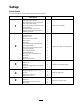
Setup Loose Parts Use the chart below to verify that all parts have been shipped. Step 1 2 3 4 5 Qty.
Step 6 7 8 9 11 Description Qty.
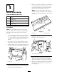
Step 5. Remove the backing and affix the self-adhesive heat shield material to the engine side of the rear panel, positioning as shown in Figure 4. Do not re-install the panel at this time. 1 Note: The heat shield material must be affixed so that the rear panel can be reinstalled to the frame without pinching the heat shield material.
Figure 8 1. Front cover 2. Heat shield 14. Install rubber grommets into the 3 holes in the rear frame mount as shown in (Figure 9). Figure 6 1. Heat shield 2. Heat shield 2 x 10 inch piece 9. Insert the seat wire harness through the slit in the heat shield. 10. Remove the backing and affix the 2 x 10 inch piece of self-adhesive heat shield between the seat latches on the bottom of the seat mount plate (Figure 6). Figure 9 1. Rubber grommets 11.
Step 2 Preparing the Engine Cooling System Parts needed for this step: 1 2 2 4 1 2 2 1 1 2 1 1 1 Cab assembly (supplied with cab model 30371) Nipple coupler Quick disconnect coupler Hose clamp Tee tting Hose clamp-large (supplied with cab model 30371) Hose clamp-small (supplied with cab model 30371) Hose adapter tting Bulkhead bracket Self-tapping screw (5/16 inch) Dust plug Dust cap Dual contact switch Figure 10 1. Cab Back panel 2. Hose labeled Pressure 2.
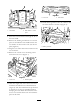
4. On the other end of the hose, measure down 20 inches (50.8 cm) from where the hose exits the frame, mark the hose and cut the hose at this location (Figure 11). This will be the return hose. 5. Insert the barb end of a nipple coupler into the pressure hose and secure with a hose clamp (Figure 12). Figure 14 1. Rear frame mount 9. Install the bulkhead bracket to the left rear frame mount with 2 self-tapping screws (5/16 inch) (Figure 15). Figure 12 1. Return hose 2. Pressure hose 3. Hose clamps 4. 5.
Figure 18 Figure 16 1. Quick disconnect coupler 2. Dust plug 3. 4. 1. 2. Nipple coupler Dust cap Radiator hose Tee tting 3. 52 inch long hose 15. Connect the 55 inch (140 cm) length of previously cut hose to the new tee fitting in the radiator hose (Figure 18 ). Secure the hose to the tee fitting with a hose clamp. Route the hose behind the radiator over flow tank, up the right side of the radiator, across the top of the radiator to the left side and under the air cleaner as shown in Figure 20.
Figure 20 1. 22–1/2 inch hose 2. 52 inch Hose 3. Cable tie Figure 22 16. Disconnect the wire and remove the thermo-switch from the left side of the engine thermostat housing (Figure 21). Discard the switch. 1. Engine thermostat housing 3. 2. Hose adapter tting 4. 22–1/2 inch (57 cm) long hose Hose clamp 18. Connect the 22–1/2 inch (57 cm) length of hose to the engine thermostat housing adapter fitting (Figure 22). Secure the hose to the adapter fitting with a hose clamp.
Step 3 Preparing the Electrical System Parts needed for this step: 1 1 2 4 Figure 23 1. Engine thermostat housing 2. Cab harness Fusible link Cable tie Cable tie (supplied with cab model 30371) Procedure Switch Route and secure the cab harness and fusible link as follows: 20. Install the new dual contact switch to the right side of the engine thermostat housing (Figure 24). 1. Insert the wires from the large harness connector down thru the right grommet in the rear frame mount (Figure 25).
Figure 28 1. Pink wire with plastic bubble (cut off end of plastic bubble) Note: If an Auxiliary Power Kit is installed on the machine, proceed as follows: Figure 26 1. Control panel cover 2. A. Unplug the pink wire from the auxiliary power kit connector. Latches B. Plug the pink wire connector into the appropriate connector on the new harness. 3.
Figure 30 1. 3. 4. 2. Floor jack 2. Install the skid plate (Figure 31) to the frame below the engine as follow: Figure 29 1. Negative battery cable (-) 2. Positive battery cable (+) Rear bumper tube Fusible link Black wire A. Mount the front of the skid plate to the skid mounting plate with 2 flange-head bolts (3/8 x 1-3/4 inches) and flange nuts (3/8 inch) (Figure 31). 10. Secure the wires to the cables with cable ties. B.
Step 5 Removing the Mower Deck Parts needed for this step: 2 2 2 2 Vertical tube support assembly Clevis pin Self-tapping screw (1/4 inch) Hose plug Procedure 1. Position a suitable floor jack under the rear bumper tube and raise the rear tires off of the ground (Figure 32). Figure 33 1. Deck frame 3. 2. Vertical tube support 3. Pivot open the floor plate (Figure 34) and secure with prop rod. Figure 32 1. Rear bumper tube 2. Clevis pin & self-tapping screw Floor jack 2.
4. Loosen the PTO drive shaft bolts and nuts. Remove the roll pin and pull the drive shaft off of the gearbox shaft (Figure 35). Figure 37 1. Deck lift cylinder Figure 35 1. Drive shaft 2. Gear box 3. 4. Bolts Roll pin 8. Disconnect the tank hose from the control valve (Figure 38). Install the cap from the winter kit valve into the control valve fitting and plug the hose with the plug supplied. 5. Remove the retaining ring securing the rear of the deck lift cylinder to the pivot pin (Figure 36).
Note: Retain 4 of the bolts for re-installation and store the remaining bolts, washers and nuts for the summer change over. Step 6 Note: The floor jack can be raised or lowered to ease removal of the bolts. Lower the floor jack completely once the bolts are removed. Installing the Winter Frame Assembly Parts needed for this step: 2 4 1 6 20 2 2 Figure 39 Hose cover Cable tie Winter frame assembly Wheel and tire assembly Lug nut Coupler pin Tracks Procedure 1.
Figure 44 1. Drive shaft 2. Frame tube Figure 42 1. Pump 2. 6. Route the hoses as follows: Pressure hosed tting (rotated 45 degrees) • Route the pressure hose under the lift cylinder and between the cylinder mounting brackets to the valve (Figure 45). 4. Remove the two screws securing the floor plate cover to the floor and remove the plate (Figure 43). • Route the tank hose along side the PTO shaft to the valve (Figure 45).
Figure 48 Figure 46 1. Pressure hose 2. Tank hose 3. Hose cover 4. 5. 6. 1. Coupler pin Cable tie Bolts Roll pin 10. Adjust the floor jack as required to install the bolts (3/4 inch) on each side (Figure 49). Torque the bolts to 265 ft-lb (359 N⋅m). 8. With the winter frame against the rear frame, raise the floor jack enough to remove the summer drive tires (Figure 47). Install the winter tires with 2 lug nuts per side. Figure 49 1. 3/4 inch bolts Figure 47 2.
Figure 50 1. Pressure hose 2. Figure 52 Tank hose 1. 12. Raise the rear of the machine until 2 jack stands can be positioned under the rear tube at a height that supports the rear tires 1 to 3 inches (2.5 to 7.5 cm) off of the ground. Washer & nut on the bogie pivot stud (2) 16. Raise the floor jack until the front tires are off of the ground high enough to install the track beneath them and support the frame with jack stands. 13. Lower the floor jack so the rear frame rests on the jack stands.
Note: You may need to move the floor jack to the rear bumper to raise the rear of the machine high enough to install the flat washer and locknut. 23. Re-install the side access covers with the screws previously removed (Figure 56). The track guides have many pinch points. Carefully grasp the rubber track on the outer edges outboard of the steel guides when moving the track. 20. Adjust the floor jack to a suitable height to install the front tire.
Step 8 Re-installing the Panels Parts needed for this step: 2 2 Corner mat (supplied with cab model 30371) Seal Procedure 1. Place the rear panel into position and align the top mounting holes with the holes in the frame cross member (Figure 59). Secure the top of the panel to the cross member with 3 screws previously removed. Figure 57 1. ROPS 2. Pin 3. Cotter pin 4. 5. Bolt & nut ROPS post 2.
Figure 60 1. Seal (2) 2. Corner mat (2) 3. Rear panel Figure 62 1. Front cover 3. Clean the right and left edges of the rear panel. Make sure all grease and/or oil is removed from the panel to assure proper adhesion. Step 9 4. Remove the backing and affix the self-adhesive seals to each edge of the rear panel (Figure 60). Make sure each seal butts up against the fuel tank side panels. 5. Install the floor plate cover (Figure 61) and the front cover (Figure 62).
Step 10 Making the Final Connections and Checking the Operation Figure 63 1. Cab door bracket 2. Door closer 3. Clip No Parts Required Procedure Note: The cab doors and windows may be removed to ease installation, decrease the lifting weight and to prevent possible damage. 1. Tighten the bolts and nuts securing the cab mount supports to the ROPS posts. 2. Connect the cab pressure and return heater hoses to the quick couplers on the rear frame mount (Figure 65). 2.
Step 11 Reading the Manuals Parts needed for this step: 1 1 1 1 1 2 1 1 1 Figure 66 1. Cab wire harness connector 2. Harness connector on the rear frame mount Operator’s Manual Parts Catalog Pre-delivery Inspection Sheet Certicate of Quality Jacking tube Jacking tube bolts Eyelet Spacer Flange nut (1/4 inch) Procedure 4. Reinstall the back panel to the cab. 1. Read the manuals. Note: Reinstall the doors and windows (if removed) and secure door closer to the cab door bracket. 2.
Product Overview Figure 67 1. 2. 3. 4. Track Front lift arm Windshield wiper Work lights 5. 6. 7. Door latch Fuel tank cap Hood Controls Become familiar with all the controls before you start the engine and operate the machine. Refer to the manual supplied with the cab for operating instructions.
Operation Note: Determine the left and right sides of the machine from the normal operating position. Think Safety First Figure 68 Please read all safety instructions and symbols in the safety section. Knowing this information could help you or bystanders avoid injury. 1. Warning— wear hearing protection Attachments Operating on wet grass, ice or slippery steep slopes can cause sliding and loss of control. Read the Operator’s Manual supplied with the attachment before operating.
Snowthrower Wire Eyelet Winter to Summer Conversion If mounting a snowthrower attachment, install the wiring eyelet as follows: 1. Start the machine and remove any attachments. Position the machine so the winter frame can be rolled away and replaced with the summer frame and the rear of the machine can be raised with a floor jack. (Cab door and side window can be removed if space is limited). Store the attachment per the instructions in the manufacturers Operator’s Manual. 1. Locate, mark and drill a .
Figure 73 1. Pressure hose 2. Tank hose 3. Hose cover 4. 5. 6. Figure 75 Cable tie Bolts Roll pin 1. Washer & nut on the bogie pivot stud 8. Position a suitable floor jack under the center of the front lift arm pivot tube. 5. Position two jack stands under the rear bumper tube at a height so that they contact or nearly contact the bumper. 9. Raise the floor jack until the rear of the machine is supported on the jack stands and the center tire swings back and nearly contacts the rear tire. 6.
Pull the tank hose back toward the rear of the frame. Figure 76 1. Pressure hose 2. Tank hose Figure 78 1. 16. Disconnect the pressure hose from the control valve (Figure 76). Cap the hose and fitting. Pull the hose back toward the rear of the frame. 17. Unplug the cab harness connector (Figure 77) and install the cap onto the connector. Pressure hose 2. Return hose 19.
Figure 80 1. Summer drive tire Figure 82 21. Install the center tires on the winter frame. 22. Install the cab jack tube into the cutouts in the cab floor (Figure 81). Tighten the jacking bolts until the tapered ends go through the hole in the floor plate and just contact the frame. 1. Cab mount 2. ROPS post 3. 4. Bolts & nuts ROPS post 26. Loosen the two front cab mounting bolts so the cab can pivot freely. 27.
Note: If the pins are tight, rotate the pins while pulling. 31. Roll the summer deck and frame into position and install the five 3/4" bolts, washers and nuts that connect the deck frame to the rear frame (Figure 86). Remove the lift cylinder pins and rear drive tires (if required) to gain access to the bolts on the right hand side. Torque the bolts to 265 foot pounds. Figure 84 1. Coupler pin Figure 86 1. 29.
Figure 89 1. Drive shaft 2. Gear box 3. 4. Bolt Roll pin 35. Route and connect the hydraulic pressure and tank hoses to the valve (Figure 90). Figure 87 1. Deck frame 3. 2. Vertical tube support Clevis pin & screw pin retainer 33. Pivot open the floor plate (Figure 88). Figure 90 1. Control valve 2. Tank hose 3. Pressure hose 36. Install the rear of the deck lift cylinder onto the pivot pin and secure with the retaining ring (Figure 91). 37.
Figure 91 1. Deck lift cylinder 2. Retaining ring 3. 4. Screw Cylinder pin & screw 38. Remove the bolts and nuts securing the cab mount supports to the ROPS posts (Figure 92). Figure 93 1. 2. 3. ROPS Pin Cotter pin 4. 5. Bolt & nut ROPS post 40. Start the machine, raise and lower the deck. Check for leaks and make sure the hoses do not rub against the frame. Summer to Winter Conversion 1. Start the machine and lower the mower deck to the lowest height of cut.
Figure 96 1. Rear bumper tube Figure 94 1. ROPS 2. Pin 3. Cotter pin 4. 5. 2. Floor jack 5. Install the vertical tube support assembly to each rear corner of the deck frame with a clevis pin and a 5-16" self-tapping screw pin retainer (Figure 97). Bolt & nut ROPS post 3. Loosely install a cab mount support to each ROPS post with two bolts (1/2 x 3 inches), two nuts (1/2 inch), two bolts (3/4 x 3–1/2 inch) and two nuts (3/4 inch) (Figure 95). Make sure the top plate hole is positioned forward.
6. Remove the retaining ring securing the rear of the deck lift cylinder to the pivot pin (Figure 98). Figure 100 1. Figure 98 1. Deck lift cylinder 2. Retaining ring 3. 4. Screw Cylinder pin Floor plate 10. Remove the roll pin and loosen the two capscrews securing the drive shaft to the gearbox shaft (Figure 101). Slide the drive shaft off the gearbox shaft. 7. Remove the screw securing the front cylinder pivot pin to the mower frame (Figure 98).
Figure 104 Figure 102 1. Control valve 2. Tank hose 3. 1. Two mounting bolts (3/4 inch), washers and nuts (Right side) Pressure hose 15. Roll the mower deck and frame forward and out of the way. 12. Disconnect the pressure hose from the control valve (Figure 102). Cap the hose and fitting with a cap and plug. Pull the hose back toward the rear of the frame. 16. Loosen the pressure hose fitting at the pump and rotate the fitting 45 degrees toward the front of the machine (Figure 105). 13.
Figure 106 1. Floor plate cover 2. Figure 108 Mounting screws 1. 18. Carefully roll the winter frame assembly into position while routing the drive shaft through the frame tube (Figure 107). Jacking bolts 19. Route the hoses as follows: • Route the tank hose under the lift cylinder and between the cylinder mounting brackets to the valve (Figure 109). • Route the pressure hose along side the PTO shaft to the valve (Figure 109).
inch) to 175-225 in-lb (20 to 25 N⋅m). Install the roll pin (Figure 110). Figure 112 1. Coupler pin Figure 110 1. Pressure hose 2. Tank hose 3. Hose cover 4. 5. 6. 23. Adjust the floor jack or rock the cab with your hands as required to install the bolts (3/4 inch) on each side (Figure 113). Torque the bolts to 265 ft-lb (359 N⋅m). Cable tie Bolts Roll pin 21. With the winter frame against the rear frame, raise the floor jack enough to remove the summer drive tires (Figure 111).
Figure 116 1. Rubber mount 2. 0.875 inch (2.2 cm) Figure 114 1. Cab mount 2. Rubber mount 27. Tighten the bolts and nuts securing the rear cab mounts to the ROPS posts (Figure 117 ). Adjust the floor jack if the bolts are binding and difficult to remove. 25. Lower the cab into position by slowly and evenly loosening the jacking bolts on each end of the jacking tube (Figure 115). Figure 117 1. 2. Figure 115 1. Jacking bolts 2. Cab jack tube Cab mount ROPS post 3. 4. Bolts & nuts ROPS post 28.
31. Lower the floor jack so the rear frame rests on the jack stands. Position the floor jack under the center of the front lift arm pivot tube. 32. Remove the flat washer (1/2 inch) and nut (1/2 inch) installed on the stud on the bogie pivot (Figure 120). Figure 118 1. Jacking bolts 2. Cab jack tube 29. Connect the hydraulic pressure and tank hoses to the valve (Figure 119). Retain the hose plugs for the summer change over.
Note: You may need to move the floor jack to the rear bumper to raise the rear of the machine high enough to install the flat washer and locknut. The track guides have many pinch points. Carefully grasp the rubber track on the outer edges outboard of the steel guides when moving the track. 39. Install the side access covers with the screws previously removed (Figure 124). 36. Adjust the floor jack to a suitable height to install the front tire.
Figure 126 1. Pressure hose 2. Return hose 42. Remove the cap and plug the cab wire harness connector into the harness on the rear frame mount (Figure 127). Figure 127 1. Cab wire harness connector 2. Harness connector on the rear frame mount 43. Start the machine. Run the lift arm up and down and check for hydraulic leaks. Check the antifreeze level and replenish as required.
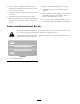
Maintenance Recommended Maintenance Schedule(s) Maintenance Service Interval After the rst 10 operating hours Maintenance Procedure • Torque the frame mounting bolts. • Torque wheel lug nuts. Every 50 hours • Lubricate grease ttings • Check the tire pressure. Every 200 hours • Torque wheel lug nuts. If you leave the key in the ignition switch, someone could accidently start the engine and seriously injure you or other bystanders. Remove the key from the ignition before you do any maintenance.
Drive System Maintenance Checking the Tire Pressure Check the tire pressure every 50 hours (Figure 130). Maintain the air pressure in the tires at 35 psi . Uneven tire pressure can cause lose of traction. If a lose of traction occurs, tire pressure may be increased to 50 psi to increase track tension. Check the tires when they are cold to get the most accurate pressure reading. Figure 129 1. PTO shaft bearings (2) 2. Hydraulic cylinder pivot pins (2) 3.
inch) and locknuts on the bogie pivot stud (Figure 132). and torque to 75 ft-lb (102 N⋅m). Note: You may need to move the floor jack to the rear bumper to raise the rear of the machine high enough to install the flat washer and locknut. Note: The front and center wheels can be removed without raising and supporting the rear of the machine. Figure 131 1. Access covers 3. Loosen and remove the locknut and flat washer from the bogie pivot weldment (Figure 132). Figure 132 1.
Storage Machine 1. Thoroughly clean the machine and cab, paying special attention to these areas: • PTO shaft assembly • All grease fittings and pivot points • Oil the spline on the PTO output shaft to prevent rusting 2. Check and adjust tire pressure; refer to Checking Tire Pressure in Drive System Maintenance, page 48. 3. Check all fasteners for looseness and tighten them as necessary. Especially torque the 5 bolts securing the winter frame to the traction unit to 265 ft-lb (359 N⋅m). 4.
Notes:
The Toro General Commercial Products Warranty A Two-Year Limited Warranty Conditions and Products Covered The Toro® Company and its afliate, Toro Warranty Company, pursuant to an agreement between them, jointly warrant your Toro Commercial Product (“Product") to be free from defects in materials or workmanship for two years or 1500 operational hours*, whichever occurs rst.