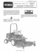
FORM NO. 3318-375 MODEL NO. 30372~ 60001 & UP COOPERATOR'S MANUAL GUARDIAN® 72° RECYCLER® j FOR GROUNDSMAN 3000 SERIES TRACTION UNITS To assure maximum safety, optimum performance, and {o gain knowledge of the product, iris essential that you or any other operator of the machine read and understand the contents of this manual before the engine is ever staved.
FOREWORD The Guardian® 72° Recycler® Cutting Deck has advanced concepts in engineering, design and safety; and if maintained properly, will give excellent service. Since this is & high~quality product, Toto is concerned about the future use of the machine and safety of the user. Therefore, read this manual to familiarize yourself with proper set—up, operation and maintenance instructions. The major sections of the manual are: 1. Safety Instructions 3. Be tore Operating 8, Lubrication 2.
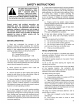
SAFETY INSTRUCTIONS The safety alert symbol means CAUTION, WARNING or DANGER — “personal safety instruction”. Read and understand the instruction because it has to do with safety. Failure to comply with the instruction may result in personal injury. Hazard control and accident prevention are dependent upon the awareness, concern, and paper training of the personnel involved in the operation, transport, maintenance, and storage of the machine.
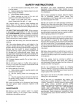
SAFETY INSTRUCTIONS C. Do not drive close to a sand rap, ditch, creek or other hazard. D. Reduce speed when making sharp turns and whee turning on hillsides. E. Avoid sudden starts and stops. F Before backing up, look to the rear and assure no one is behind the machine. G. Watch out for traffic when near or crossing roads. Always yield the right—of ~way. 15. If engine stalls or machine loses headway and cannot make it to the top of a slope, do not tum machine around.
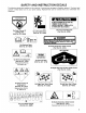
SAFETY AND INSTRUCTION DECALS The following decals are installed on the machine. If any become damaged or illegible, replace it. The decal part number is listed below and in your parts catalog. Replacements can be ordered from your Authorized Toto Distributor. DANG KEEP HANDS aod FEET AWAY | & CAUTION BLADE RETAINING BOLTS MUST BE TORQUED T0 85-110 ft-lbs. CHECK BLADE BOLT TORQUE AFTER STRIKING ANY SOLID ABJECT. a0 — On Front of Cutting Unit On gar! ot On Left Caster Arm {(Part No. nutting Uni (Part No.
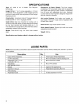
SPECIFICATIONS Type: 72" width of cut, & blades. Toto Recycle technology. Height Of Cut: 1”7 to §” inches adjustable in 1/2 inch increments. Front adjustment is with snapper pin and grooves in castor shaft. Rear adjustment is with hanger brackets and pin. Construction: Housing is made of 12 gauge steel and reinforced with x 10 gauge channel. Cuvier Drive: Gear box mounted on cutting unit is driven by PTO shaft. Power is transmitted to the blades by one hex B8 section belt.
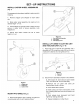
INSTRUCTIONS INSTALL CASTOR WHEEL ASSEMBLIES (Fig. 1) The snapper pins have been installed in castor arms for shipping. 1. Remove snapper pins shipped on each castor earn. 2. Slide castor wheel assembly into castor arm to desired height—of—out, 3. Insert snapper pin through holes in castor arm and groove in castor shaft to secure assembly. Lock snapper pin. 4. Assure both castor wheels are set at same height—of—cut. Figure 1 1. Snapper pin 2. Castor arm 3. Castor wheal MOUNT PTO SHIELD (Fig. 2) 1.
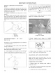
SET-UP INSTRUCTIONS Figure 4 Lat eh Cover Headcase Lever Shiatsu otter s 3. Move cutting uniting front of traction unit so ball joint brackets align with mounting holes in castor ans, Adjust ball joint brackets in or out equally until they easily fine up with deck mounting holes. 4. Mount each ball joint bracket to castor arm with (2) 71614 x 3" Ig. corkscrews and lockouts. Figure § 1. Ball dint Braggart 2. Casio A 8, Tighten ball joint jam nuts. . Tighten release lever with 2 8/4" (19mm) wrench. F.
SET—UP INSTRUCTIONS Figure 8 1. Lat oh Plate 2. tats Rog 8. Rotate front of deck upward and insert latch rod inch front hole {service position) in latch plate. 9. Loosen larch plate flange head cap screws and adjust latch plate position if required. GREASE CUTTING UNIT Before the cutting unit is operated, it must be greased to assure proper lubricating characteristics: refer to Lubrication section of manual. Failure to properly grease the cutting unit will result in premature failure of critical parts.
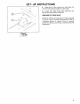
BEFORE OPERATING CHECK LUBRICANT IN GEAR BOX {Fig. 9) The gear box is designed 1o operate with SAE 80—80 wi. gear lube. Although the gear box is shipped with lubricant from the factory, check the level before aerating the curling unit. 1. Position the machine and cutting unit on a elev! surface. 2. Remove check plug from side of gear box and make sure lubricant is up to bottom of hole.
BEFORE OPERATING ADJUSTING SKIDS (Fig. 14 1. Adjust skids by loosening flange nuts, positioning as desired and re—tightening flange nuts Figure 14 1. Skid 2. Range mt ADJUSTING DESK PITCH (Fig. 15 Deck pitch is the difference in from the front of the blade plane to the back of the blade plane. TOR recommends a blade pitch of .25 inches, Thais the back of the blade plane is .25 inches higher than the front. 1. Position machine on a level surface on shop floor, 2. Set deck to the desired height—of—cut. 3.
OPERATING INSTRUCTIONS OPERATING TIPS 1. Mow When Grass Is Dry—Mow either in the late morning to avoid the dew, which causes grass clumping or in late afternoon to avoid the damage that can be caused by direct sunlight on the sensitive, freshly mowed grass. 2. Select The Proper Height—of—cut Sating To Suit Conditions — Remove approximately one inch or na more than 1/3 of the grass blade when cutting. In exceptionally lush and dense grass you may have to raise your height—of—cut to the next setting. 3.
LUBRICATION GREASE BEARING, BUSHINGS AND GEAR BOX (Fg. 18} The culling unit must be lubricated regularly. If machine is operated under normal conditions, lubricate castor bearings and bushings with No. 2 general purpose lithium base grease or molybdenum base grease, after every 8 hours of operation or daily, whichever comes first. Lubricate filings immediately after every washing, regardless of the interval listed. 1.
MAINTENANCE A CAUTION To prevent accidental staring of the engine, while performing maintenance, shut engine off and remove key from ignition switch, DISCONNECT CUTTING UNIT FROM TRACTION UNIT (Fig. 17-18) Mote: Implements are heavy and may require two people to handle. 1. Start tractor and raise deck to highest possible position and turn off engine. 2. Remove hair pin cotter and clevis pin securing height—of—cut straps 10 rear height—of—cut brackets, 1. Height-of-Cut Straps 3.
MAINTENANCE 7. Install other il arm on tractor by rotating deck towards tractor, aligning lift arm 1o tractor am and repeating step 5. if latch does not fall into slot in traction unit lit arms the arms are not lined up. A, If lift arms on traction unit are not at the correct height for deck arms 1o slide on, push up or down on fight arm castings farm behind the front tires unit deck arm lines up and slides on, B. I lift arms on deck do not line up side 1o side.
MAINTENANCE SERVICING FRONT BUSHINGS IN CASTOR FORKS (Fig. 23) The castor forks have bushings pressed into the top and bottom of the casting and after many hours of operation, the bushings will wear. To check the bushings, move castor fork back and forth and from side to side. If castor spindle is loose around the bushings, bushings are worn and must be replaced. 1. Start tractor and raise deck to highest possible position and turn off engine. 2.
MAINTENANCE REMOVING CUTTER BLADE (rig. 25) The blade must be replaced if a solid object is hit, the blade is or if the blade is bent. Always use genuine TROD replacement blades to be sure of safety and optimum performance. Never use replacement blades made by other manufacturers because they could be dangerous. 1. Raise cutting unit to highest position, shut the engine off and engage the parking brake. 2. Remove hair pin cotters and clevis pins securing height—of—cut straps to rear of deck. 3.
MAINTENANCE 6. To check blade for being straight and parallel, lay blade on a level surface and check its ends. Ends of blade must bs slightly lows than the center, and cutting edge must be lower than the heel of the blade. This blade will produce good quality of cut and require minimal power from the engine. By contrast a blade that is higher at the ends than the center, or if cutting edge is higher than the heel, the blade is bent or warped and must be replaced. 7.
IDENTIFICATION AND ORDERING MODEL AND SERIAL NUMBERS The cutting deck has two identification numbers: a model number and a serial number. The two numbers are stamped into a plate on front channel of the mower deck, under cover. In any correspondence concerning the mower, supply the model and serial numbers to assure that correct information and replacement parts are obtained. 47058 To order replacement parts from an authorized TOR Distributor, supply the following information: 1.
The Toto Promise A One Year Limited Warranty The Toto Company promises to repair your TOR product if defective in materials or workmanship.