Form No. 3351–377 Guardian 72 inch Recycler for Groundsmaster 3000 Series Traction Units Model No. 30372—Serial No. 240000001 and Up Operator’s Manual Register your product at www.Toro.
Contents Introduction . . . . . . . . . . . . . . . . . . . . . . . . . . . . . . . . Safety . . . . . . . . . . . . . . . . . . . . . . . . . . . . . . . . . . . . . Safe Operating Practices . . . . . . . . . . . . . . . . . . . Safety and Instruction Decals . . . . . . . . . . . . . . . Specifications . . . . . . . . . . . . . . . . . . . . . . . . . . . . . . . Loose Parts . . . . . . . . . . . . . . . . . . . . . . . . . . . . . . . . . Set Up Instructions . . . . . . . . . . . . . . . . . . . . . . . .
• Check interlock switches daily for proper operation (Refer To Section in Traction Unit Operator’s Manual on Checking Interlock Switches). Do not rely entirely on safety switches -shut off engine before getting off seat. If a switch fails, replace it before operating the machine. The interlock system is for your protection, so do not bypass it. Replace all interlock switches every two years. Interlock switches should be adjusted so: Safety This machine meets or exceeds the B71.
• Lower the cutting unit to the ground and remove key from ignition switch whenever machine is left unattended. • Using the machine demands attention, and to prevent loss of control: • Mow only in daylight or when there is good artificial light. Maintenance • Drive slowly and watch for holes or other hidden hazards. • Remove key from ignition switch to prevent accidental starting of the engine when servicing, adjusting or storing the machine.
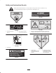
Safety and Instruction Decals Safety decals and instructions are easily visible to the operator and are located near any area of potential danger. Replace any decal that is damaged or lost. 85-6410 43-8480 93-7818 93-6697 1. Read the Operator’s Manual. 1. Warning—read the Operator’s Manual for instructions on torquing the blade bolt/nut to 115–149 N⋅m (85–110 ft.-lb.). 2. Add SAE 80w–90 (API GL-5) oil every 50 hours. 93–0299 1. Do not step 106-6753 1.
104-0131 93–4690 1. Read the Operator’s Manual. 1. Height of cut 93-7814 1. Entanglement hazard, belt—stay away from moving parts. 93–4691 1. Height of cut 94–3392 1.
Specifications Blades: Three 25.18” long, .25” thick, heat–treated steel. Suspension & Castor Wheels: Two front castors, consisting of 10” pneumatic wheel and tire assembly with sealed ball bearings. Rear of deck is suspended from lift arms with adjustable deck rake. Hydraulic counter balance and lift system designed integral with deck for maximum flotation. Type: 72” width of cut, 3 blades. Toro Recycler technology. Height Of Cut: 1” to 5” inches adjustable in 1/2 inch increments.
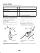
Loose Parts Note: Use the chart below to verify that all parts have been shipped. Qty. Description Use Castor wheel assembly 2 Installing the castor wheel assemblies PTO shield 1 Self tapping screws 4 Lift arm assembly 2 Installing the lift arms Decals 9 Apply for CE applications Operator’s manual 1 Read before operating the machine Parts catalog 1 Use for ordering replacement parts Mounting the PTO shield Set Up Instructions 3.
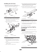
Installing the Lift Arms 3. Move cutting unit in front of traction unit so ball joint brackets align with mounting holes in castor arms. Adjust ball joint brackets in or out equally until they easily line up with deck mounting holes. 1. Adjust ball joint in each lift arm assembly until a dimension of 2.50 inches from end of lift arm to center of ball joint is attained. Do not tighten jam nut. 4. Mount each ball joint bracket to castor arm with (2) 7/16–14 x 3” lg. capscrews and 7/16–14 locknuts. 2 2.
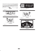
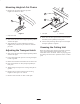
Mounting Height-of-Cut Chains 1. Remove hair pin cotter and clevis pin from height-of-cut bracket on deck. 2 1 1 Figure 8 Figure 7 1. Latch plate 2. Latch rod 1. Height of cut chain 8. Rotate front of deck upward and insert latch rod into front hole (service position) in latch plate. 2. Start tractor and raise deck to highest possible position and turn off engine. 9. Loosen latch plate flange head capscrews and adjust latch plate position if required. 3.
Before Operating 3. Insert snapper pin into castor arm and through groove in castor shaft to get desired height–of–cut. Checking the Lubricant in the Gear Box The gear box is designed to operate with SAE 80–90 wt. gear lube. Although the gear box is shipped with lubricant from the factory, check the level before operating the cutting unit. Figure 11 1. Position the machine and cutting unit on a level surface. 4. Remove hair pin cotter and clevis pin securing height–of–cut chain to rear of deck. 2.
Adjusting Anti-Scalp Rollers Adjusting the Deck Pitch Note: If cutting unit is to be used in the 1” or 1–1/2” height–of–cut setting, cutting unit rollers must be repositioned in the top bracket holes. Deck pitch is the difference in height–of–cut from the front of the blade plane to the back of the blade plane. TORO recommends a blade pitch of .25 inches. That is the back of the blade plane is .25 inches higher than the front. To adjust front and rear rollers: 1.
Operation Always Mow With Sharp Blades – A sharp blade cuts cleanly and without tearing or shredding the grass blades like a dull blade. Tearing and shredding causes the grass to turn brown at the edges which impairs growth and increases susceptibility to diseases. Operating Tips Mow When Grass Is Dry–Mow either in the late morning to avoid the dew, which causes grass clumping or in late afternoon to avoid the damage that can be caused by direct sunlight on the sensitive, freshly mowed grass.
Maintenance 1. The cutting unit has bearings and bushings that must be lubricated, and these lubrication points are: front castor shaft bushings (2), blade spindle bearings (3), idler arm pivot and right and left push arm ball joints (Fig. 16). Greasing the Cutting Unit The cutting unit must be lubricated regularly. If machine is operated under normal conditions, lubricate castor bearings and bushings with No.
Connecting the Cutting Unit to the Traction Unit 4. Raise seat and open needle valve. This allows lift arms to float freely. 1. Center traction unit in front of cutting unit on any flat hard surface. 2. Raise seat and open needle valve. This allows lift arms to float freely. 3. Adjust lift arms heights making sure that the machined surface on top of each traction unit lift arm is parallel to ground (Fig. 19).
Replacing the Drive Belt 12. Start tractor and raise deck to highest possible position and turn off engine. The blade drive belt, tensioned by the spring loaded idler, is very durable. However, after many hours of use, the belt will show signs of wear. Signs of a worn belt are: squealing when belt is rotating, blades slipping when cutting grass, frayed edges, burn marks and cracks. Replace the belt if any of these conditions are evident. 13.
5. Route new belt around spindle pulleys and thru idler pulley assembly, as shown in figure 23. 5 6 1 6 Figure 23 3 4 6. Reposition gear box plate on deck channels while routing belt around gear box pulley. Mount gear box plate to deck channels with capscrews and nuts previously removed. 2 7. Reinstall idler arm bracket to idler arm with cotter pin and clevis pin. Hook spring onto idler arm bracket.
3. Check the bearings, spacer and inside of wheel hub for wear. Replace defective parts as required. 4. Grasp end of blade using a rag or thickly padded glove. Remove blade bolt, anti–scalp cup and blade from spindle shaft. 4. To assemble the castor wheel, push bearing into wheel hub. Slide spacer into wheel hub. Push other bearing into open end of wheel hub to captivate the spacer inside the wheel hub. 5. Install castor wheel assembly between castor forks and secure in place with capscrew and locknut.
7. Install blade—sail facing (up) toward cutting unit– with anti–scalp cup and blade bolt. Tighten blade bolt to 85–110 ft–lb. Correcting Cutting Unit Mismatch If there is mismatch between the blades, the grass will appear streaked when it is cut. This problem can be corrected by making sure the blades are straight and all blades are cutting on the same plane. 1. Using a 3 foot long carpenters level, find a level surface on the shop floor. 2.
The Toro General Commercial Products Warranty A Two-Year Limited Warranty Conditions and Products Covered The Toro Company and its affiliate, Toro Warranty Company, pursuant to an agreement between them, jointly warrant your Toro Commercial Product (“Product”) to be free from defects in materials or workmanship for two years or 1500 operational hours*, whichever occurs first.