
Installation Instructions
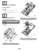


3.Installtheharnessclipsintotheholesinthebottom
ofthecarrierframe.
4.Routetheharnessundertheoorandalongtheright
framechanneltothedualrateasher.
5.Inserttheharnessclipsintotheframeholes.
6.Plugtheharnessconnectorintothedualrateasher
connector.
7.Routetheharnessunderthecontrolpanel.
8.Plugtheharnessconnectorsintothelightandturn
signalswitchconnectors.Plugtheturnsignalharness
connectorintothefrontswitch.
9.Connecttheharnesswireringterminaltotheauxiliary
powerunitground.
10.Plugtheharnesspowerconnectorintotheauxiliary
powerunitpowersource.
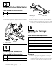
11.Installthe15ampfuseintothefuseblock.
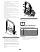
12.Insertarubbergrommetintoeachframecrossmember
hole(
Figure8).
g018284
1
2
Figure8
1.Grommet
2.Framecrossmember
13.Routetheharnessundertheframeandupbehindthe
seat.
14.RoutetheharnessuptherightROPStube,intothe
crossmember,andoutthroughthegrommets.
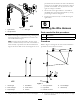
15.Connecttheharnesstotherearashersandworklight.
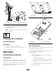
16.Securetheharnesstothecrossmemberwith2cable
ties.Ifthereisaharnessalreadysecuredtothecross
member,securethenewharnesstoitusingacabletie
(
Figure9).
17.SecuretheharnesstotheROPSwith5cableties
(
Figure9).
g018285
Figure9
Note:Usecabletieswherenecessarytopreventtheharness
frompossibledamage.
7
InstallingtheSMVEmblem
Partsneededforthisprocedure:
1
SMVemblem
1
SMVemblembracket
2
Bolt(1/4x3/4inch)
2Locknut
2U-bolt
2
Locknut(3/8–16)
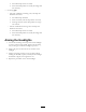
Procedure
1.Mounttheslowmovingvehicle(SMV)emblemtothe
SMVemblembracketwith2bolts(1/4x3/4inch)
and2locknuts(Figure10).
5