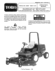
MODEL NO. 20384~ 80001 3 UP FORM NO. 3317918 Rav. A OPERATOR'S MANUAL L GUARDIAN® 84” RECYCLER® ] JAF OR GROUNDSMASTER® 3000 SERIES TRACTION UNITS To assure maximum safety, optimum performance, ant to gain knowledge of the product, Ris essential that you or any other aerator of the machine read and understand the contents of this manual before the engine is aver started.
FOREWORD The Guardian® 84" Recycler® Cutting Deck has advanced concepts in engineering, design and safety; and if maintained properly, will give excellent service. Since this Is & high--quality product, Toto is concerned about the future use of the machine and safety of the user. Therefore, read this manual to familiarize yourself with proper set—up, operation and maintenance instructions. The major sections of the manual are: 5. Lubrication 6. Maintenance 1. Safely Instructions 2. Set—up Instructions 3.
SAFETY INSTRUCTIONS The safety alert symbol means CAUTION, WARNING or DANGER “personal safety instruction”. Read and under— stand the instruction because it has to do with safety. Failure to comply with the instruction may result in personal injury. Hazard control and accident prevention are dependent upon the awareness, concern, and proper training of the personnel involved in the operation, transport, maintenance, and storage of the machine.
SAFETY INSTRUCTIONS G. Do not drive close to a sand trap, ditch, creak or other hazard. D. Reduce speed when making sharp turns and when turning on hillsides. E. Avoid sudden starts and stops. F. Before backing up, look to the rear and assure no one is behind the machine, G. Waite out for traffic when near or crossing roads. Always yield the right—of —way. 15, if engine sills or machine loses headway and cannot make it to the top of a slope, do not tum machine around.
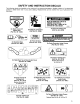
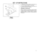
SAFETY AND INSTRUCTION DECALS The following decals are installed on the machine. If any become damaged or illegible, replace it. The decal part number is listed below and in your parts catalog. Replacements can be ordered from your Authorized Toto Distributor. WG BLADE RETAINING BOLTS MUST BE TORQUED T0 85-110 ft-Abs. CHECK BLADE BOLT TORQUE AFTER STRIKING ANY SOLID OBJECT. sarge On Front of Cutting Unit On Each Corner Of On Right & Left Covers Part No, 68-8340) Pant ‘;‘o "23_ B480) (Part No.
SPECIFICATIONS Type: 84" width of cut, § blades, 3 blade center section, and 2 one blade wings. Toto Recycle technology. Mowing Rate: Mows up to 4.4 acres/hr at 8.5 mph. Trimming Ability: Deck is centered on tractor with 15 inches of over hang on each side. Uncut circle is 24.0 inches on both left and right with no brakes. Height Of Cut: 1-5 inches adjustable in 1/2 inch increments. Front adjustment is with snapper pin and grooves in castor shaft. Rear adjustment is with hanger brackets and pin.
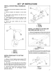
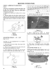
SET—UP INSTRUCTIONS INSTALL CASTOR WHEEL ASSEMBLIES (Fig. 1) The snapper pins have been installed in castor arms for shipping. 1. Remove snapper pins shipped on each castor arm. 2. Slide castor wheal assembly into castor arm to desired height—of—cut. 3. insert snapper pin through holes in castor arm and groove in castor shaft to secure assembly. Lock snapper pin. 4. Assure both castor wheels are set at same height—of—cut. Figure 1 1. Snapper pin 2. Castor arm 3.
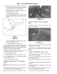
SET--UP INSTRUCTIONS 3. Recurs lift arm assembly to traction unit as follows: A, With engine off, raise seat and open needle valve. This allows lift arms to float freshly. B. Remove hair pin cotter and clevis pin securing latch caver to lift am. G, Pivot release lever upward. 1 elide cutting unit lift arm note traction unit lift arm, inserting shaft latch into slot in action unit fitter. Figure 5 1. Larch Cover 2. Release Lever 3. Shalt larch E.
SET-UP INSTRUCTIONS Figure 8 1. Latch Plate 2. Lat oh Rod 8. Rotate front of deck upward and insert latch rod into front hole (service position} in latch plate. 9. Loosen larch plate flange head cap screws and adjust latch plate position if required. GREASE CUTTING UNIT Before the cutting unit is operated, it must be greased to assure proper lubricating characteristics: refer io Lubrication section of manual.
BEFORE OPERATING CHECK LUBRICANT IN GEAR BOX (Fig. 9 The gear box is designed o operable with SAE 8090 wt. gear lube. Although the gear box is shipped with lubricant from the factory, check the level before operating the cutting unit. 1. Position the machine and cutting unit on a level surface. 2. Removes check plug from side of gear box and make sure lubricant is up 1o bottom of hole.
BEFORE OPERATING ADJUSTING ANTI-SCALP ROLLERS (Fig. 14) Anti—scalp rollers should be located in upper holes for 1 and 1-1/2 inch heights—of—cut and lower holes for 2 1o § inch heights—of—cut. Five riflers are located on the deck, three under the main deck and one on each wing. 1. Circumstantial rollers by removing lock nut and bolt, positioning as desired and reinstalling lock nut and bolt. ADJUSTING DECK PITCH (rig.
OPERATING INSTRUCTIONS OPERATING TIPS 1. Mow When Grass Is Dry—Mow either in the late morning to avoid the dew, which causes grass clumping or in fate afternoon to avoid the damage that can be caused by direct sunlight on the sensitive, freshly mowed grass. 2. Select The Proper Height—of -cut Setting To Suit Conditions — Remove approximately one inch or no more than 1/3 of the grass blade when cutting. In exceptionally lush and dense grass you may have to raise your to the next setting. 3.
LUBRICATION GREASE BEARINGS, BUSHINGS AND GEAR BOX (Fig. 18) The cutting unit must be lubricated regular. i machine is operated under normal conditions, lubricate castor bearings and bushings with No, 2 general purpose lithium base grease or molybdenum base grease, after every 8 hours of operation or daily, whichever comes first. Lubricate fittings immediately after every washing, regardless of the interval listed. 1.
MAINTENANCE A CAUTION To prevent accidental starting of the engine, while performing maintenance, shut engine off and remove key from Ignition switch. DISCONNECT CUTTING UNIT FROM TRACTION UNIT (Fig. 17-1%) Mote: Implements are heavy and may require two people to handle. 1. Start tractor and raise deck io highest possible position and turn off engine. 2. Remove hair pin cotter and clevis pin securing height—of—cut straps fo rear height -of —cut brackets. Figure 17 T, Straps 3.
MAINTENANCE 7. Install other fight arm on factor by rotating deck towards tractor, aligning it arm fo tractor arm and repeating step 5. If latch does not fall into slot in traction unit lift arm the arms are not lined up. A, Militarism on traction unitary not at the correct height for deck arms to slide on, push up or down on lift arm castings from behind the front tires until deck arm line up and slide on. B. If lift arms on deck do not line up side to side.
MAINTENANCE 4. Remove retaining ring, washer and wave washer securing castor shaft to castor fork. Remove shaft from fork. 5. Insert pin punch into top or bottom of castor fork and drive bushing out of fork. Repeat for other bushing. Clean inside of forks to remove dirt, Figure 22 1. Front Castor Fork 4. Wave Washer 2. Retaining Ring 8. Castor Shaft 3. Washer 8§, Bushings 6. Apply grease to Inside and outside of new bushings. Using a hammer and flat plate, drive bushings into fork. 7.
MAINTENANCE Figure 24 1. Blade obit 2. Anti~Scalp Cup 5. Install blade—sail facing (up) toward cutting unit— with anti—scalp cup and blade bolt. Tighten blade bolt t0 85—110 fib. A WARNING Do notary to straighten a blade that is bent, and never weld a broken or cracked blade. Always use a new blade to assure continued safety certification of the product. INSPECTING AND SHARPENING BLADE (Fig. Raise cutting unit to highest position, shut the engine off and engage the parking brake. 2.
MAINTENANCE CORRECTING CUTTING UNIT MISMATCH If there is mismatch between the blades, the grass will appear streaked when it is cut. This problem can be corrected by making sure the blades are straight and all blades are cutting on the same plane. 1. Position machine on a level surface on the shop floor. 2. Release belt tension on belts. 3. Raise deck to transport position and lock transport latch, 4.
Va-861 IDENTIFICATION AND ORDERING MODEL AND SERIAL NUMBERS The cutting deck has two identification numbers: a model number and a serial number. The two numbers are stamped into a plate on front channel of the mower deck, under cover. In any correspondence concerning the mower, supply the model and serial numbers to assure that correct information and replacement parts are obtained, To order replacement parts from an authorized TOR Distributor, supply the following information: 1.
The Toto Promise A One Year Limited Warranty The Tore Company promises to repair your TORSO product if defective in materials or workmanship.