FORM NO. 3319-384GB Rev A MODEL NO.
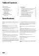
Table of Contents SPECIFICATIONS SAFETY INSTRUCTIONS Symbol Glossary BEFORE OPERATING Check Lubricant in Gear Box Adjusting Height-of-Cut Adjusting Skids Adjusting Rollers Adjusting Deck Pitch OPERATING INSTRUCTIONS Operating Tips 2 3 6 9 9 9 9 10 10 11 11 MAINTENANCE Lubrication Disconnecting Cutting Unit from Traction Unit Connecting Cutting Unit to Traction Unit Changing Gear Box Lubricant Replacing Drive Belt Servicing Front Bushings in Castor Forks Servicing Castor Wheels and Bearings Removing Cutter
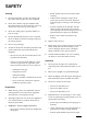
SAFETY Training • Refuel outdoors only and do not smoke while refueling. 1. Read the instructions carefully. Be familiar with the controls and the proper use of the equipment. 2. Never allow children or people unfamiliar with these instructions to use the lawnmower. Local regulations may restrict the age of the operator. • Add fuel before starting the engine. Never remove the cap of the fuel tank or add petrol while the engine is running or when the engine is hot.
• if the machine starts to vibrate abnormally (check immediately). and during tight turns; • stay alert for bumps and hollows and other hidden hazards; • never mow across the face of the slope, unless the lawnmower is designed for this purpose. 14. Disengage drive to attachments when transporting or not in use. 15. Stop the engine and disengage drive to attachment 6. Use care when pulling loads or using heavy equipment.
Sound & Vibration Levels Sound Levels This unit has an equivalent continuous A-weighted sound pressure at the operator ear of: 88 dB(A), based on measurements of identical machines per 84/538/EEC. This unit has a sound power level of 104 dB(A)/1pW, based on measurements of identical machines per procedures outlined in Directive 79/113/EEC and amendments. Vibration Levels This unit has a vibration level of 2.5 m/s2 at the posterior, based on measurements of identical machines per ISO 2631 procedures.
Symbol Glossary Caustic liquids, Poisonous Electrical shock, chemical burns to fumes or toxic electrocution fingers or hand gases, asphyxiation Crushing of whole body, applied from above High pressure High pressure Crushing of Crushing of spray, erosion of spray, erosion of fingers or hand, toes or foot, force flesh flesh force applied from applied from above above Crushing of Crushing of fingers Crushing of leg, Crushing of torso, force or hand/, force force applied whole body applied from side applied
Consult technical Fasten seat manual for proper belts service procedures Safety alert triangle Outline safety alert symbol Head protection Hearing Caution, toxic must be worn protection must risk be worn First aid Flush with water Engine Transmission Hydraulic system Exhaust gas Level indicator Liquid level Brake system Filter Oil Temperature Coolant (water) Intake air Failure/ Malfunction Start switch/ mechanism On/start Read operator’s Fire, open light manual and smoking prohibited Pre
n/min Engine start Engine stop Engine failure/ malfunction Engine rotational Choke speed/frequency Primer (start aid) Electrical preheat Transmission (low temperature oil start aid) NH L F Transmission oil pressure Transmission oil temperature Transmission Clutch failure/malfunction Neutral High Low Forward RP 1 2 3 Reverse Park First gear Hydraulic oil filter Hydraulic oil temperature Hydraulic oil Parking brake failure/malfunction Fuel Unleaded fuel Headlights Unlock Diesel fuel Pow
Before Operating CHECK LUBRICANT IN GEAR BOX (Fig. 1) The gear box is designed to operate with SAE 80-90 wt. gear lube. Although the gear box is shipped with lubricant from the factory, check the level before operating the cutting unit. 1. 2. Position the machine and cutting unit on a level surface. Remove the check plug from the side of the gear box and make sure the lubricant is up to the bottom of the hole.
ADJUSTING ROLLERS (Fig. 6) Rollers should be located in the upper holes for 2.5 and 3.8 cm heights of cut and lower holes for 5 to 12.7 cm heights of cut. Five rollers are located on the deck, three under the main deck and one on each wing. Figure 5 1. Adjust the rollers by removing the lock nut and bolt, positioning as desired and then installing the lock nut and bolt. ADJUSTING DECK PITCH (Fig.
Operating Instructions OPERATING TIPS 1. Mow When Grass Is Dry—Mow either in the late morning to avoid the dew, which causes grass clumping or in late afternoon to avoid the damage that can be caused by direct sunlight on the sensitive, freshly mowed grass. 2. Select The Proper Height-of-Cut Setting To Suit Conditions— Remove one inch or no more than 1/3 of the grass blade when cutting. In exceptionally lush and dense grass you may have to raise your height of cut to the next setting. 3.
8. Deck Pitch—Toro recommends a blade pitch of 6.4 mm. A pitch larger than 6.4 mm will result in less power required, larger clippings and a poorer quality of cut. A pitch less than 6.4 mm will result in more power required, smaller clippings and a better quality of cut. Maintenance LUBRICATION 1. The cutting unit has bearings and bushings that must be lubricated, and these lubrication points are: gage wheels (2) (Fig.
CAUTION To prevent accidental starting of the engine while performing maintenance, shut of the engine and remove the key from the ignition switch. DISCONNECTING THE CUTTING UNIT FROM THE TRACTION UNIT (Fig. 10–12) Note: Implements are heavy and may require two people to handle. 1. Start the tractor and raise the deck to the highest possible position and turn off the engine. 2. Remove the hair pin cotter and clevis pin securing the height-of-cut straps to the rear height-of-cut brackets. 3.
2. Raise the seat and open the needle valve. This allows the lift arms to float freely. 8. Move the deck from side to side to check for tightness and re-tighten the latches, if required. 3. Adjust the lift arms heights, making sure that the machined surface on top of each traction unit lift arm is parallel to the ground (Fig. 11). (Raise or lower the lift arm casting by pushing up or down from behind the front tires or by using a wrench in front of the tractor) 9.
REPLACING DRIVE BELTS (Fig. 14–15) The blade drive consists of three belts—one main drive belt and two wing belts. The main drive belt is tensioned by a fixed idler with a spring adjustment. The wing belts have spring-loaded idlers. All belts are very durable but after many hours of use, the belt will show signs of wear. Signs of a worn belt are: squealing when belt is rotating, blades slipping when cutting grass, frayed edges, burn marks and cracks. Replace any belt if any of these conditions are evident.
tube. 3. Remove the locknut from the capscrew holding the castor wheel assembly between the castor fork. Grasp the castor wheel and slide the capscrew out of the fork. 4. Remove the retaining ring, washer and wavy washer securing the castor shaft to the castor fork. Remove the shaft from the fork. 5. Insert a pin punch into the top or bottom of the castor fork and drive the bushing out of the fork. Repeat for the other bushing. Clean inside of the forks to remove dirt. 6.
5. Install the castor wheel assembly between the castor forks and secure in place with capscrew and locknut. REMOVING CUTTER BLADE (Fig. 18) The blade must be replaced if a solid object is hit, the blade is out of balance or if the blade is bent. Always use genuine TORO replacement blades to be sure of safety and optimum performance. Never use replacement blades made by other manufacturers because they could be dangerous.
away the metal that connects the flat and curved parts of the blade, check the blade before using the machine. If wear is noticed (Fig. 19-B), replace the blade: refer to Removing The Cutter Blade. DANGER If the blade is allowed to wear, a slot will form between the sail and flat part of the blade (Fig. 17C). Eventually a piece of the blade may break off and be thrown from under the housing, possibly resulting in serious injury to yourself or a bystander. 5. 6. 7.
are stamped into a plate on the front channel of the mower deck, under cover. In any correspondence concerning the mower, supply the model and serial numbers to assure that correct information and replacement parts are obtained. To order replacement parts from an authorized TORO Distributor, supply the following information: 1. Model and serial numbers of the machine. 2. Part number, description and quantity of parts desired.