Form No. 3388-972 Rev A Debris Blower Groundsmaster® 7200/7210 Traction Unit Model No. 30393—Serial No. 315000001 and Up Register at www.Toro.com.
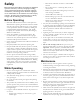
Figure 2 Introduction 1. Safety alert symbol The debris blower is mounted to a ride-on machine which is intended to be used by professional, hired operators in commercial applications. It is primarily designed to use wind power to quickly clear large areas of unwanted debris on well-maintained lawns in parks, golf courses, sports fields, and on commercial grounds. This manual uses 2 other words to highlight information.
Safety Hazard control and accident prevention are dependent upon the awareness, concern, and proper training of the personnel involved in the operation, transport, maintenance, and storage of the machine. Improper use or maintenance of the machine can result in injury or death. To reduce the potential for injury or death, comply with the following safety instructions. Before Operating • Read and understand the contents of this Operator’s • • • • • • Manual before operating the machine.
Use cardboard or paper to find hydraulic leaks. Hydraulic fluid escaping under pressure can penetrate skin and cause injury. Fluid accidentally injected into the skin must be surgically removed within a few hours by a doctor familiar with this form of injury or gangrene may result. Authorized Toro Distributor check the maximum engine speed with a tachometer. • The engine must be shut off before checking the oil or adding oil to the crankcase.
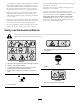
105-4593 1. Entanglement hazard, shaft—do not remove cover while parts are moving, keep all guards in place. 114–4054 1. Warning—read the Operator’s Manual, do not operate the machine without the cross pin in place.
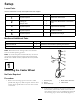
Setup Loose Parts Use the chart below to verify that all parts have been shipped. Procedure Description Use Qty. 1 No parts required – Mount the castor wheel. 2 Debris blower assembly Locking pin Hair pin cotter 1 1 1 Mount the debris blower to the traction unit. No parts required – Adjust the link assembly. No parts required – Grease the blower. No parts required – Install the front weight. 3 4 5 Media and Additional Parts Description Use Qty.
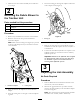
5. Insert the locking pin through the adapters and secure with a hairpin cotter (Figure 5). 3. Make sure the castor wheel assembly tire is inflated to 35 to 50 psi. 2 Mounting the Debris Blower to the Traction Unit Parts needed for this procedure: 1 Debris blower assembly 1 Locking pin 1 Hair pin cotter 1 G006618 Procedure 1. Remove any attachment from the rear of the machine. Figure 5 2. Back the traction unit into position behind the attachment adapter. 1.
5 Installing the Front Weight No Parts Required 2 Procedure CAUTION 3 When an attachment is not installed on the machine, loose weights must be removed. Never operate the machine with no attachment installed and front weights on the machine. 1 Use the following weight charts to determine the correct amount of front weight required for your machine. G00381 1 Figure 6 1. 1.5 to 2.0 mm (0.060 to 0.080 inch) 3. Adjustment nut 2.
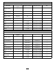
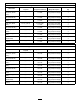
72-inch width of cut Groundsmaster 7200/7210 with NO hard canopy Additional front weight required Weight part number(s) Rear QAS and no attachment (Model 30377) 0 kg (0 lb) n/a QAS finish grader / box rake (Model 08754) 0 kg (0 lb) n/a Steel drag mat (Model 08757) 0 kg (0 lb) n/a Tooth rake (Model 08751) 0 kg (0 lb) n/a Tooth rake with spring rake (Model 08752) 0 kg (0 lb) n/a Coco drag mat (Model 08758) 30.
62-inch width of cut Groundsmaster 7200/7210 with NO hard canopy Attachment Additional front weight required Weight part number(s) Weight description Qty Rear QAS and no attachment (Model 30377) 30.4 kg (67 lb) 114-4090 and 114-4096 front weight bracket and 19 kg (42 lb) front weight 1 1 QAS finish grader / box rake (Model 08754) 68.5 kg (151 lb) 114-4090 and 114-4096 front weight bracket and 19 kg (42 lb) front weight 1 3 Steel drag mat (Model 08757) 68.
Product Overview Operation Specifications Adjusting the Discharge Opening Note: Specifications and design are subject to change without notice. Net weight The discharge opening (Figure 7) is adjustable to increase or decrease air output velocity and volume. Decreasing the discharge opening size increases the velocity. 107 kg (235 lb) 1. Loosen discharge opening deflector mounting screws (Figure 7).
1 Figure 8 1. Float 2. Power-down 3. Lift/Lower Operating Tips G003783 WARNING Figure 9 Discharged air has considerable force and could cause injury or loss of footing. 1. Pry slot • Stay away from discharge opening when machine is operating. • Keep bystanders away from discharge opening when machine is running. Practice blowing material. It is advisable to blow the same direction the wind is blowing to prevent material from blowing back into the cleared area.
Maintenance Greasing the Attachment Adapter Lubrication If the locking lever on the attachment adapter does not pivot freely and easily, apply a light coat of grease to the area shown in Figure 12. The debris blower has bearings and bushings that must be lubricated regularly. If the machine is operated under normal conditions, lubricate the bearings with #2 general-purpose, lithium-based grease after every 8 hours of operation or daily, whichever comes first.
3 2 4 G003815 1 Figure 14 1. Motor coupler 3. Set screw (2 each) 2. Fan coupler 4. Coupler spider 1 G003817 Figure 16 1. Fan mounting nut 3. Tighten the capscrews and the nuts securing the mounting brackets together and to the blower housing. 4. Remove the alignment tool and finish assembly. Servicing the Castor Arm Bushings Torquing Fasteners If the blower is ever disassembled, the following fasteners must be torqued as specified. Also, apply Loctite 242 to the threads before installing.
Figure 17 1. Bushings 2. Castor arm tube Figure 18 1. Locknut 2. Washer 3. Tire spanner 5. Apply grease to the inside and outside of the new bushings. Using a hammer and flat plate, drive the bushings into the mounting tube. 6. Inspect the castor spindle for wear and replace it if it is damaged 4. Castor fork 5. Castor wheel 6. Bolt 2. Remove one of the outer bearings from the wheel hub and allow the inner bearing to fall out (Figure 19). Remove the bearing from the opposite side of the wheel hub. 7.
Notes: 16
Notes: 17
Notes: 18
Declaration of Incorporation The Toro Company, 8111 Lyndale Ave. South, Bloomington, MN, USA declares that the following unit(s) conform(s) to the directives listed, when installed in accordance with the accompanying instructions onto certain Toro models as indicated on the relevant Declarations of Conformity. Model No. 30393 Serial No.
Toro General Commercial Product Warranty A Two-Year Limited Warranty Conditions and Products Covered The Toro Company and its affiliate, Toro Warranty Company, pursuant to an agreement between them, jointly warrant your Toro Commercial product (“Product”) to be free from defects in materials or workmanship for two years or 1500 operational hours*, whichever occurs first. This warranty is applicable to all products with the exception of Aerators (refer to separate warranty statements for these products).