MODEL NO. 30450 50001 & UP MODEL NO. 30455~ 50001 & UP MODEL NO. 30401 50001 & UP FORM NO. 3316848 Rev. A OPERATOR’S MANUAL Yo understand this product, and for safety and optimum performance, read this manual before starting the engine. Pay special attention to SAFETY INSTRUCTIONS highlighted by this symbol. A it means CAUTION, WARNING or DANGER personal safety instruction. Failure to comply with the instruction may result in personal injury.
FOREWORD This operator’s manual has instructions on safety, proper set—up and operation, adjustments and maintenance. Therefore, anyone involved with the product, including the operator, should read and understand this manual, Major sections are: Safety Instructions — Before Operating ~ Operating Instructions ~ Maintenance — Schematics ~ Seasonal Storage This manual emphasizes safety, mechanical and general product information. DANGER, WARNING and CAUTION identify safety messages.
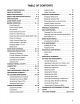
TABLE OF CONTENTS PRODUCT IDENTIFICATION TABLE OF CONTENTS .. SAFETY INSTRUCTIONS SAFETY AND INSTRUCTION DECALS SPECIFICATIONS LOOSE PARTS CHART 10 BEFORE OPERATING Check Engine Oll Check Cooling System 11 Fill Fuel Tank Check Hydraulic Circuit Oif Check Front Axis Off Level Check Rear Axis Lubricant (Model 30455 only) 12 Check Tire Pressure 13 Check Morgue of Wheel Nuts .. .. .
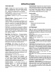
A SAFETY INSTRUCTIONS The GROUNDS MASTER 455-D was tested and certified by TOR for compliance with the specifications of the American National Standards Institute. Although hazard control and accident prevention partially are dependent upon the design and configuration of the machine, these factors are also dependent upon the awareness; concern, and proper draining of the personnel involved in the operation, transport, maintenance, and storage of the machine.
A SAFETY INSTRUCTIONS 15. Traverse slopes carefully. Do not start or stop suddenly when traveling uphill or downhill. Never shift axle when moving. Machine must be on a fiat surface and / or brakes must be engaged to prevent freewheeling. 16, Operator must be skilled and trained in how to drive on hillsides. Failure to use caution on slopes or hills may cause loss of control and vehicle to tip or roll possibly resulting in personal injury or death. 17.
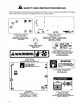
A SAFETY AND INSTRUCTION DECALS The following safety and instruction decals are affixed to the traction unit. if any decal becomes illegible or damaged, install a new decal. Part numbers are listed below and in your Parts Catalog. song, M ON RIGHT HAND CONSOLE ON RIGHT HAND CONSOLE { Part No, 841450 } { Part No.
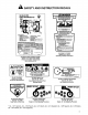
A SAFETY AND INSTRUCTION DECALS GM 455-D 2WD @] M QUICK REFERENCE AID o READ AND UNDERSTAND OPERATOR'S. 2 MANUAL BEFORE STINGER THIS ACHIEVE. @3 WEY DESPERADOES DEB HI ASTER WU BIN ‘ADAPTATIONS EN UHA COOPERATION SEGUES, USE EXTREME CAUTION ON HILLS 'AND SLOES, €SEAT BELT SHOULD ALLAYS BE USED WEN OPERATING WFH ROLL-GRUE SECTION STRICTURE, SEAT YO 2 CHECKLIST. SRR FRONT AXLE Oil REVEILLE 0.
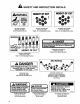
A SAFETY AND INSTRUCTION DECALS WARNING SHIELD MISSING DO NOT USE et & HEIGHT OF CUT HEIGHT OF CUT ON Lower PTO Pulley (Part No. 88-8950) ‘Shield Missing Do Not Use ON LEFT CASTOR ARM {Part No. B-0720) Adjusting Procedure Smsfi@i Low_ o3 111572 253 35 HIGH 8} 25—3—36—4—45—5RANGE HEIGHT OF CUT | ON LEFT CASTOR ARM {Part No. 86 -0780} Height—of Cut Adjusting Procedure A DANGER HIGH PRESSURE HYDRAULIC HOSES OPERATE ONLY IF THIS COVER ASSEMBLY IS IN PLACE, 993 QN Access Panel (Part No.
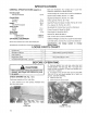
SPECIFICATIONS TRACTION UNIT Engine: Peugeot, four cylinder, 1.9 liter {1800 coy displacement, liquid cooled diesel engine. 23.5:1 compression ratio. Low idle — 1600 rpm, high die ~ 3000 rpm. Qil capacity is 5.3 gts. with filter. Cooling System: Capacity is 3.5 gal. of 50/50 mixture of Peugeot recommended anti—freeze. Fuel System: Capacity is 14 gal. diesel fuel. Hydraulic System: Reservoir capacity is 6.5 gal. Replaceable spin—on filter element. Traction System: Ground speed: Low Range; 0 8.5 mph (0 ~ 5.
SPECIFICATIONS GENERAL SPECIFICATIONS (approx.): Roll Over Protection Kit, Contact Your Local Toto Distributor (Standard on Model 30455) Overall Length; 4 Post Canopy. Kit, Contact Your Laval Toto Distributor With deck installed 134in. Spark Arrest or Muffler, Part No, 77 -3990 Overall Width: ) Segmented Wheel Kit, Part No. 76~ 1380 m’v’jfign J5I0 brake tight Ki, Part No, 927763 Height: 53 in. Ear Box Pulley (Tip Speed 14,500}, Part No. 86-3100 With TOPS installed 82in. Uncleaner Kit, Part No.
BEFORE OPERATING CHECK COOLING SYSTEM (Fig. 3) Capacity of stern is 3.5 gal. 1. Park machine on a level surface. Release hood latch and open hood. 2. Check coolant level. Coolant level should above mounting tabs on degassed tank, when engine is cold. Figure 3 1. Degassed Tank 2. Mounting Tabs 3. It coolant is low, remove degassed dank cap and add a 50/80 mixture of water and Peugeot recommended anti~freeze (Toto Part No. 93-7213).
BEFORE OPERATING 1. Park machine on a level surface and stop engine. Make sure machine has been operated so oil is warm. Release hood latch and open hood. Check level of oil by viewing sight gauge. if oils visible in gauge, ofl level is sufficient, 2. If oll level is not visible in gauge, remove cap from hydraulic oil reservoir and slowly add Mobil DTE 26 or equivalent hydraulic ol until level reaches middle {maximum) of sight gauge. DO NOT OVER Fill. Figure 5 1. Sight Gauge 2.
BEFORE OPERATING CHECK TIRE PRESSURE The tires are over—inflated for shipping. Therefore, release some of the alr to reduce the pressure. Correct air pressure in the front and rear tires is 20 psi. IMPORTANT: Maintain even pressure in all tires to assure a good quality—of—cut and proper machine performance. DO NOT UNDER INFLATE. CHECK TORQUE OF WHEEL NUTS OR BOLTS ADJUSTING HEIGHT-OF-CUT (Fig. 10-12) The height—of—cut is adjustable from 1 o 5 inches in 1/2 inch increments.
BEFORE OPERATING Figure 10 3. Spacers 4. Washer (center deck only) 1. Front Castor Wheel 2. HOC Cap REAR CASTOR WHEELS 1. Remove hairpin cotter and H.O.C. pin securing rear castor pivot arm to deck bracket, Figure 11 1. Rear Castor Rivet 2. Align the pivot arm holes with selected bracket holes in the deck frame, install H.O.C. pin and secure with hairpin cotter. REAR DECK STRAPS 1.
KNOW YOUR CONTROLS Cutting Unit Engagement Switch (Fig. 14) ~ Used to start and stop cutting unit operation. Lift switch and move forward 1o actuate cutting unit. Center deck will engage first followed by wing decks engaging approximately one second later. o r Figure 14 1. Suiting Unit Engagement 8. Fuel Gauge Switch 9. Hour Meter 2. Glow Plug Indicator 10. Engine Ol Pressure 3. Charge Indicator Warning Light 4. Key Switch 11, Engine Coolant Temperature 5. Throttle Control Warning Light 6.
KNOW YOUR Axle Shift Lever (Fig.16) — Located on right side of console, lever defects front drive mode. Pull blackout knob, move lever rearward for mowing operation and forward for transport operation, then release knob o lock selection. Lever must be in LO position to mow. Middle position (N} is for towing. IMPORTANT: On model 30455, lever must be in LO position to operate in 4-wheal drive. CAUTION: Machine must be on a flat surface and brakes engaged when shifting axle farm Hi to LO position. Figure 17 1.
OPERATING INSTRUCTIONS Note: Priming fuel filter without opening bleed screw may damage priming plunger. 4. Spurn priming plunger until resistance is felt. Try to start engine. If engine does not start repeat step 3. Figure 19 1. Primer Plunger 2, Breed Screw Note: It may be necessary to bleed the air out of the fuel line between the fuel filter / water separator and the injection pump. To do this, loosen the fitting on the injection pump (Fig. 20) and repeat bleeding procedure. Figure 20 4.
OPERATING INSTRUCTIONS Warning System ~ [f a warning light comes on during operation, stop the machine immediately and correct the. problem. before. continuing. operation.. Serious damage could occur if the machine is operated with a malfunction, Mowing — When you are at the area to be mowed, release cutting unit transport latches. Move axis shift lever rearward to Mow position and throttle to FAST so engine is running at maximum speed. Lift engagement switch and move forward 1o engage cutting units.
CRIB NATION GREASING (Fig. 21-35) The traction unit-and cutting unit have grease fittings that must be lubricated regularly with No. 2 General Purpose Lithium Base Grease. If machine is operated under normal conditions, lubricate all grease filings after every 25 hours of operation. Lubricate all grease fittings immediately after every washing, regardless of interval listed. Note: Grease castor wheels daily. 1.
DAILY MAINTENANCE CHECKLIST Daily Maintenance: (duplicate this page for routine use} Check proper section of Operator’s Manual for fluid specifications maintenance Daily Maintenance Check For Week Of Check stem » MON TUES WED | THURS FRI o SUN »~ Safety Interlock Operation = Brake Operation » Engine Oil Level Fuel Level v Cooling System Fluid Level Drain Water/Fuel Separator » Optional Air Filter Cleaner » Radiator & Screen for Debris! » Unusual Engine Noises? w» Unusual Operating Noises Hydraulic System Oi
MAINTENANCE SCHEDULE Minimum Recommended Maintenance Intervals Maintenance Procedure Maintenance Interval & Service Every Every Inspect Air Filter, Dust Cup and Baffle Every Every 400hrs 800hrs Lubricate All Grease Fittings 50hrs 100hrg Check Cutting Unit Gear Box Oil Level $ Change Engine Oil and Filter Check Battery Level/Cable Connections inspect Co cling System Hoses Service Air Cleaner Filter Element Inspect PTG and Cutting Unit Belts Check Electric Deck Clutches Adjustment Check Electric PTO Clutch Ad
Ali R CLEANER MAINTENANCE A\ caution Before servicing or making adjustments to the machine, stop engine and remove key from the switch. GENERAL MAINTENANCE PRACTICES Inspect air cleaner and hose periodically to maintain maximum engine protection and to ensure maximum service life. 1. Assure hose between air cleaner and intake manifold is clamped securely in place. Replace the hose if it is cracked or punctured. 2. Check air cleanser body for dents and other damage which could possibly cause an air leak.
AR CLEANER INSPECTING FILTER ELEMENT (Fig. 36) 1. Place bright light inside filter, 2. Rotate filter slowly while checking for cleanliness, ruptures, holes, and tears. Replace defective filter element. ENGINE CAUTION Before servicing or making adjustments io the aching, stop engine and remove key from the switch, ENGINE O AND FILTER (Fig. 37-38) Change oil and filter initially after the first 50 hours of operation, thereafter change ofl and filter every 100 hours. 1. Remove drain plug {Fig.
ENGINE MAINTENANCE A DANGER Because diesel fuel is highly flammable, use caution when storing or handling it. Do not smoke while filling the fuel tank. Do not fill fuel tank while engine is running, hot, or when machine is in an enclosed area. Always fill fuel tank outside and wipe up any spilled diesel fuel before starting the engine. Store fueling a clean, safety-approved container and keep cap in place. Use diesel fuel for the engine only; not for any other purpose.
ENGINE MAINTENANCE Note: Upper portion of fan shroud may be easily unbolted from machine to simplify cleaning. B install rear screen and tighten knobs: IMPORTANT. Do not use water fo clean engine, as garage may occur. 2. W Maintaining Cooling System Capacity of the system is 3.5 gal. Always protect cooling system with a 50/50 solution of warier and Peugeot recommended anti—freeze. DO NOT USE WATER ONLY IN COOLING SYSTEM. A. After every 100 operating hours, tighten hose connections.
HYDRAULIC MAINTENANCE 5. With wing decks raised, center deck down and oil warm, look into sight gauge (Fig. 44). if hydraulic oil is not visible, add enough oil to raise level to middies {maximum of sight gauge. To prevent over filling, do Figure 44 1. Sight Gauge REPLACING HYDRAULIC FILTER (Fig. 45) Initially, change filter after the first 50 operating hours, thereafter, every 800 operating hours or annually, whichever comes first Only the Toto replacement filter (Part No.
HYDRAULIC MAINTENANCE 5. Steering Circuit has a normal relief setting of approximately 1200 psi @ high idle and warm oil. 8. Wing deck cutting unit Counterbalance normal setting is approximately 350—400 psi @ high idle and when oil is warm. Figure 47 1. Change Pressure 1, Counterintelligence Circuit 2. Steering Circuit Figure 49 1. Counterbalance (Wing Decks) a0 ADJUSTING TRACTION DRIVE FOR NEUTRAL (Fig. 50) The machine must not creep when traction pedal is released.
AXLE MAINTENANCE CAUTION Before servicing or malign adjustments to the machine, stop engine and remove key from the switch. CHANGING FRONT AXLE LUBRICANT (Fig. 51) After every 800 hours of operation the ail in the front axle must be changed. 1. Position machine on a level surface. 2. Clean area around the drain plug (Fig. 51). Figure 51 1. Front Ate Drain Ply 3. Remove plug allowing oil to drain into drain pans 4. After oil is drained, reinstall drain plug into axle. 5.
BRAKE MAIN TEN ADJUSTING SERVICE BRAKES (Fig. 54) Adjust the service brakes when there is more than of "free travel” of the brake pedal, or when the rakes do not work effectively. Free travel is the distance the brake pedal moves before braking resistance Is felt. 1. To reduce free travel of brake pedals, tighten newton brake rod adjuster,1/2 turn at a time, until desired “free play” in pedal is achieved. PT.0. MAINTENANCE A\ caution Before servicing or making adjustments to the machine, stop engine and rem
ERECTILE MAI TENANTED Ab caution Before servicing or making adjustments to the machine, stop engine and remove key from the switch. BATTERY CARE IMPORTANT: Before welding on the machine, disconnect ground cable from the battery 1o prevent damage o the electrical system. Note: Check battery condition weekly or after every 100 hours of operation. Keep terminals and entire ¢ ¢ battery case clean because a dirty battery will Figure 58 discharge slowly. To clean the battery, wash the entire 1. ACC Fuse 3.
CUTTING UNIT MAINTENANCE A\ caution To prevent accidental starting of the engine, while performing maintenance, shut engine off and remove key from ignition switch. GENERAL MAINTENANCE Note: Although not required for normal maintenance procedures, the cutting unit may be pivoted (tilted} to a upright position. Should you desire to tilt the cutting unit, use the following procedure: To Pivot (Tilt) Cutting Unit Upright: 1. Drive machine onto ramps to raise front of machine. 2.
CUTTING UNIT MAINTENANCE 5. Remove (4) cap screws, flat washers and flange nuts securing ball joint mounts to castor arms on cutting unit. Figure 61 3, Ball Joint Mount 4. Caps crows & Washers 1. Push Arm 2, Castor Arm 6. Roll the cutting unit away from the traction unit. Alternate Method 1. Lower center and wing cutting units o the ground, set parking brake and stop engine. 2. Disconnect (3) hydraulic lines {quick couplets) and wire harness at rear of deck. 3.
CUTTING UNIT MAINTENANCE A\ caution Check for proper operation of the safety doors each time the deck is cleaned and repair as needed. BLADE ADJUSTMENT (Fig. 64-65) To assure proper operation of the cutting unit, there must be .25 +.12” clearance between the tips of the wing and center cutting unit blades. 1. Raise cutting unit so blades are visible and block center deck section so it cannot fall accidentally. Wing decks must be horizontal to center cutting unit. 2.
CUTTING UNIT MAINTENANCE Fo Remove Wing Deck Delis & WARNING tidier pulley spring loaded, use caution when relieving spring tension on wing belt. 2. To relieve tension on wing belt, pull back on tidier pulley unit holes in idler adjuster tube and tube sleeve are aligned. Thread a cap screw into holes retaining parts. Figure 67 1. Opting Loaded Idler Pulley 2. Stationary Inter Pulley 3. Remove hair pin cotter securing clutch rod to front of cutting deck and disconnect rod from deck.
CUTTING UNIT MAINTENANCE ADJUSTING DECK CLUTCH (Fig. 71) The deck cliches are adjustable to ensure proper engagement and blade braking. Check clutch adjustment after the first 50 hours of operation, thereafter; every 200 hours. Adjust if required. 1. To adjust clutch, tighten or loosen lockouts on flange studs. 2. Check adjustment by inserting feeler gauge thru slots next to flange studs. 3. The proper disengaged clearance between the clutch plates is .011 ~ .021 inches.
CUTTING UNIT MAINTENANCE Figure 74 3, Bearing (2) 4. Bearing Spacer 1. Castor whee! 2. Front Caster Fork Figure 75 3, Bearing (2} 4. Bearing Spacer 1. Castor wheel 2. Rear Caster Pivot Arm Figure 76 3. Bearing (2) 4. Bearing Spacer 1. Castor wheel 2. Rear Caster Pivot Arm 2. Remove bearing from whets! hub and allow bearing spacer to fall out. Remove bearing from opposite side of wheel hub. 3. Check the bearings, spacer and inside of wheel hub for wear. Replace defective parts 4.
CUTTING UNIT MAINTENANCE 2. Examine citing ends of the blade carefully, especially where the flat and curved parts of the blade meet (Fig. 78—A). Since sand and abrasive material can wear away the metal that connects the flat and curved parts of the bide, check the blade before using the machine. f wear is noticed (Fig. 78— B}, replace the bide: refer to Blade Removal and Installation, page 40. FLAT PART OF BLADE A SAIL SLOT FORMED Figure 78 2. Inspect cutting edges of all blades.
PREPARATION FOR SEASONAL STORAGE Traction Unit 1. Thoroughly clean the ration unit; cutting -units and the engine. 2. Check the tire pressure. Inflate all tires to 20 psi. 3. Check all fasteners for looseness; tighten as necessary. 4. Grease or oil all grease fittings and pivot points. Wipe up any excess lubricant, &. Lightly sand and use touch—up paint on painted areas that are scratched, chipped, mistrusted. Repair any dents in the metal body. 8. Service the battery and cables as folios: a.
The Toto Promise A Limited Warranty The Toto Company promises to repair your Model 30450 or 30465 TOR GROUNDSMASTER® MOWER, and its cutting unit, if defective in materials or workmanship. The following time periods from the date of purchase apply: Model 30450 or 30455 2 Years or 1500 operational hours, whichever comes first. The cost of parts, labor and transportation are included.