Form No. 3418-761 Rev A Base 62in Mower Groundsmaster® 3320/3280-D Traction Unit Model No. 30403—Serial No. 401420001 and Up Model No. 30404—Serial No. 401420001 and Up Register at www.Toro.com.
WARNING CALIFORNIA Proposition 65 Warning This product contains a chemical or chemicals known to the State of California to cause cancer, birth defects, or reproductive harm. The engine exhaust from this product contains chemicals known to the State of California to cause cancer, birth defects, or other reproductive harm. g243406 Figure 1 Introduction Model No.
Contents Safety Safety ....................................................................... 3 General Safety ................................................... 3 Safe Operating Practices.................................... 4 Safety and Instructional Decals .......................... 5 Setup ........................................................................ 7 1 Preparing the Machine..................................... 7 2 Installing a Completion Kit................................
Safe Operating Practices • Read the Operator’s Manual for the traction unit and other training material carefully. Be familiar with the controls, safety signs, and the proper use of the equipment. If the operator or mechanic cannot read the language of this manual, it is the owner's responsibility to explain this material to them. • Become familiar with the safe operation of the equipment, operator controls, and safety signs.
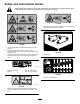
Safety and Instructional Decals Safety decals and instructions are easily visible to the operator and are located near any area of potential danger. Replace any decal that is damaged or missing. decal117-4979 117–4979 1. Entanglement hazard, belt—stay away from moving parts, keep all guards and shields in place. decal120-6604 120-6604 1. Thrown object hazard—keep bystanders away from the machine. 2.
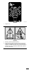
decal108-1986 108-1986 1. Height of cut decal115-4505 115-4505 1. Warning—read the Operator's Manual. 2. Tipping hazard—lower the cutting unit when driving down slopes. For 2 wheel drive units, add a 16 kg (35 lb) rear weight to GM 3280D units and a 32 kg (70 lb) rear weight to GM 3320 units. For 4 wheel drive 3280 D units, add a 16 kg (35 lb) rear weight.
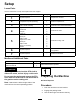
Setup Loose Parts Use the chart below to verify that all parts have been shipped. Procedure Description 1 2 3 4 5 6 7 Use Qty. No parts required – Prepare the machine. Completion kit (sold separately) 1 Install a completion kit. Castor wheel assembly 2 Install the castor wheel assemblies.
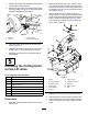
2 Installing a Completion Kit Parts needed for this procedure: 1 Completion kit (sold separately) Procedure Install 1 of the following 62-inch or 72-inch completion kits to the base deck using the instruction provided in the kit: g008866 Figure 3 • Model 30303, 72-inch Rear Discharge • Model 30304, 72-inch Guardian 1. Tensioning cap 4. Axle mounting holes 2. Spacers 5. Castor wheel 3. Thrust washers • Model 30305, 62-inch Rear Discharge 2.
3. Remove the wheel nuts and slide the wheel and tire assembly off of the studs. 4. Mount a lift arm to the pivot bracket with a pivot pin and a cotter pin (Figure 4). Mount the lift arm with the bend positioned outward. 2. Move the lift lever to the FLOAT position. Push a lift arm down until the holes in the lift arm line up with the holes in the castor arm bracket and the height of cut rod can be inserted into the lift arm pads (Figure 5). 3.
7. Install the height of cut collars onto the height of cut rods and secure with the clevis pins and hairpin cotters (Figure 5). Position the head of the clevis pin toward the front of the deck, if possible. 8. Install a bolt (1/2 x 3/4 inch) and a washer to top of each height of cut rod (Figure 5). 7 Greasing the Machine No Parts Required 6 Procedure Before operating the machine, it must be greased to ensure proper lubricating characteristics; refer to 7 Greasing the Machine (page 10).
Product Overview Operation Specifications Note: Determine the left and right sides of the machine from the normal operating position. Note: Specifications and design are subject to CAUTION change without notice. Width of Cut 1.575 m (62 inches) or 1.829 m (72 inches) Height of Cut Adjustable from 25 to 127 mm (1 to 5 inches) in 13 mm (1/2 inch) increments Net Weight Model 30403–190 kg (420 lbs.) Model 30404–231 kg (510 lbs.
Adjusting the Height-of-Cut The height-of-cut is adjustable from 25 to 127 mm (1 to 5 inches) in 13 mm (1/2 inch) increments. To adjust the height-of-cut, position the castor wheel axles in the upper or lower holes of the castor forks, add or remove an equal number of spacers from the castor forks and secure the height of cut collar to the desired holes in the height of cut rod. 1. Start the engine and raise the cutting unit off the floor so that you can change the height-of-cut.
Adjusting the Cutting Unit Pitch Cutting unit pitch is the difference in height-of-cut from the front of the blade plane to the back of the blade plane. Use a blade pitch of 6 mm (1/4 inch). That is the back of the blade plane is 6 mm (1/4 inch) higher than the front. g012231 Figure 10 1. Height-of-cut rod 3. Clevis pin and hairpin cotter 2. Height-of-cut collar 6. 1. Park the machine on a level surface. 2. Engage the parking brake. 3. Shut off the engine and remove the key. 4.
Adjusting the Skids Correcting Cutting Unit Mismatch The skids should be mounted in the lower position when operating in height of cuts greater than 64 mm (2-1/2 inches) and in the higher position when operating in height of cuts lower than 64 mm (2-1/2 inches). Due to differences in grass conditions and the counterbalance setting of the traction unit, it is advised that grass be cut and appearance checked before formal cutting is started.
Operating Tips Mow When Grass Is Dry Mow either in the late morning to avoid the dew, which causes grass clumping, or in late afternoon to avoid the damage that can be caused by direct sunlight on the sensitive, freshly mowed grass. Select the Proper Height-of-Cut Setting to Suit Conditions Remove approximately 25 mm (1 inch) or no more than 1/3 of the grass blade when cutting. In exceptionally lush and dense grass, you may have to raise the height-of-cut to the next setting.
Maintenance Recommended Maintenance Schedule(s) Maintenance Service Interval Maintenance Procedure After the first 2 hours • Tighten the castor wheel nuts. After the first 10 hours • Tighten the castor wheel nuts. • Torque the blade bolts. Before each use or daily 1 • Check the blades. Every 50 hours • • • • • • • Lubricate all bearings and bushings. Lubricate the grease fittings.1 Check the gearbox oil level. Tighten the castor wheel nuts. Torque the blade bolts.
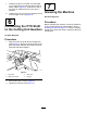
g012234 Figure 17 • Idler arm shaft bearings (Figure 17) • Lift arm pivots, front (2) (Figure 18) g010548 Figure 20 1. Dipstick/fill plug Separating the Cutting Unit from the Traction Unit 1. Position the machine on level surface, lower the cutting unit to the floor, move the lift lever to the Float position, shut the engine off, and engage the parking brake. 2. Remove the bolt and washer mounted to the top of each height of cut rod (Figure 21).
Mounting the Cutting Unit to the Traction Unit 1. 2. 3. 4. g012237 Figure 22 1. Lift arm 3. Hairpin cotter 2. Clevis pin 4. Castor arm bracket 5. Position the machine on a level surface and shut the engine off. Move the cutting unit into position in front of the traction unit. Slide the male PTO shaft into the female PTO shaft (Figure 23). Move the lift lever to the FLOAT position.
and the castor arm bracket (Figure 24). Insert end of cotter pin into the slot in the castor arm tab to retain cotter pin. 5. Apply grease to the inside and outside of the new bushings. Using a hammer and flat plate, drive the bushings into the mounting tube. 6. Repeat the procedure on the opposite lift arm. 6. 7. Start the traction unit and raise the cutting unit. Inspect the castor spindle for wear and replace it if damaged. 8.
Checking for a Bent Blade 1. Position the machine on a level surface. Raise the cutting unit, engage the parking brake, put the traction pedal in neutral, put the PTO lever in the Off position, shut off the engine, and remove the ignition key. Block the cutting unit to prevent it from accidentally falling. 2. Rotate the blade until the ends face forward and backward. Measure from the inside of the cutting unit to the cutting edge at the front of the blade (Figure 27), and remember this dimension.
1. Position the machine on a level surface. Raise the cutting unit, engage the parking brake, put the traction pedal in neutral, put the PTO lever in the OFF position, shut off the engine, and remove the ignition key. 2. Examine the cutting ends of the blade carefully, especially where the flat and curved parts of the blade meet (Figure 29). Since sand and abrasive material can wear away the metal that connects the flat and curved parts of the blade, check the blade before using the machine.
4. of the blades and add shims until the tips of the blades are within the required dimension. Route the new belt around the spindle pulleys and idler pulley assembly as shown in Figure 33. Important: Do not use more than 3 shims at any 1 hole location. Use decreasing numbers of shims in adjacent holes if more than 1 shim is added to any 1 hole location. 7. Install the belt covers. Replacing the Drive Belt The blade drive belt, tensioned by the spring loaded idler pulley, is very durable.
Notes:
Declaration of Incorporation The Toro Company, 8111 Lyndale Ave. South, Bloomington, MN, USA declares that the following unit(s) conform(s) to the directives listed, when installed in accordance with the accompanying instructions onto certain Toro models as indicated on the relevant Declarations of Conformity. Model No. Serial No.