
Operator's Manual


3.Removethewheelnutsandslidethewheeland
tireassemblyoffofthestuds.
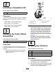
4.Mountaliftarmtothepivotbracketwithapivot
pinandacotterpin(Figure4).Mounttheliftarm
withthebendpositionedoutward.
g012393
Figure4
1.Pivotpin3.Pivotbracket
2.Liftarm
4.Brakereturnspring
5.Hookthebrakereturnspringtothetabonthe
liftarm(Figure4).
6.Installthewheelandtireassembly.Torquethe
wheelnutsto102to108N·m(75to80ft-lb).
7.Repeattheprocedureontheoppositesideof
themachine.
5
InstallingtheCuttingUnits
ontheLiftArms
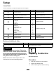
Partsneededforthisprocedure:
4Thrustwasher
4
Clevispin
2Hairpincotter
2
Height-of-cutcollar
2
Clevispin
2Hairpincotter
2
Bolt(1/2x3/4inch)
2Washer
Procedure
1.Movethecuttingunitintopositioninfrontofthe
tractionunit.
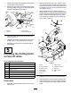
2.MovetheliftlevertotheFLOATposition.Push
aliftarmdownuntiltheholesintheliftarmline
upwiththeholesinthecastorarmbracketand
theheightofcutrodcanbeinsertedintothelift
armpads(Figure5).
3.Securetheliftarmtothecastorarmwith2
thrustwashers,aclevispinandahairpincotter.
Positionthethrustwashersbetweentheliftarm
andthecastorarmbracket(Figure5).Insert
endofcotterpinintotheslotinthecastorarm
tabtoretaincotterpin.
g012229
Figure5
1.Liftarm
7.Hairpincotter
2.Castorarmbracket8.Height-of-cutcollar
3.Height-of-cutrod
9.Clevispin
4.Liftarmpads
10.Hairpincotter
5.Thrustwashers11.Bolt
6.Clevispin
4.Repeattheprocedureontheoppositeliftarm.
5.Startthetractionunitandraisethecuttingunit.
6.Pushdownontherearofthecuttingunitand
inserttheheightofcutrodsthroughtheliftarm
pads.
9