Form No. 3363-199 Rev A Base 62in and 72in Mower Groundsmaster® 3320/3280-D Traction Units Model No. 30403—Serial No. 310000001 and Up Model No. 30404—Serial No. 310000001 and Up To register your product or download an Operator's Manual or Parts Catalog at no charge, go to www.Toro.com.
Contents Introduction Introduction................................................................. 2 Safety ........................................................................... 3 Safe Operating Practices ....................................... 3 Toro Mower Safety ............................................... 4 Safety and Instructional Decals ............................. 6 Setup............................................................................ 8 1 Installing a Completion Kit ..........
Safety – Use only an approved container. – Never remove fuel cap or add fuel with engine running. Allow engine to cool before refueling. Do not smoke. This machine meets or exceeds CEN standard EN 836:1997, ISO standard 5395:1990, and ANSI B71.4-2004 specifications in effect at the time of production. – Never refuel or drain the machine indoors. • Check that operator’s presence controls, safety switches and shields are attached and functioning properly.
Toro Mower Safety • Lightning can cause severe injury or death. If lightning is seen or thunder is heard in the area, do not operate the machine; seek shelter. The following list contains safety information specific to Toro products or other safety information that you must know that is not included in the CEN, ISO, or ANSI standard. • Use care when loading or unloading the machine into a trailer or truck. • Use care when approaching blind corners, shrubs, trees, or other objects that may obscure vision.
pressure. Use paper or cardboard, not your hands, to search for leaks. Hydraulic fluid escaping under pressure can have sufficient force to penetrate the skin and cause serious injury. • Before disconnecting or performing any work on the hydraulic system, all pressure in the system must be relieved by stopping the engine and lowering the cutting units to the ground.
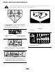
Safety and Instructional Decals Safety decals and instructions are easily visible to the operator and are located near any area of potential danger. Replace any decal that is damaged or lost. 106-6753 1. Thrown object hazard—keep bystanders a safe distance from the machine. 2. Cutting/dismemberment hazard of hand or foot, mower blade—stay away from moving parts. 108-1988 1. Belt routing 93-6697 1. Read the Operator’s Manual. 2. Add SAE 80w-90 (API GL-5) oil every 50 hours. 100-5622 1.
108-1986 1. Height of cut 115-4505 1. Warning—read the Operator’s Manual. 2. Tipping hazard—lower the cutting unit when driving down slopes. For 2 wheel drive units, add a 16 kg (35 lb) rear weight to GM 3280D units and a 32 kg (70 lb) rear weight to GM 3320 units. For 4 wheel drive 3280 D units, add a 16 kg (35 lb) rear weight.
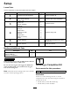
Setup Loose Parts Use the chart below to verify that all parts have been shipped. Procedure 1 2 3 4 5 6 Description Use Qty. Completion kit (sold separately) 1 Install a completion kit. Castor wheel assembly 2 Install the castor wheel assemblies.
• Model 30303, 72 inch Rear Discharge 3 • Model 30304, 72 inch Guardian 2 Installing the Lift Arms Parts needed for this procedure: Installing the Castor Wheel Assemblies Parts needed for this procedure: 2 1 Lift arm, right 1 Lift arm, left 2 Pivot pin assembly 2 Cotter pin Castor wheel assembly Procedure Procedure The thrust washers, spacers, and tensioning caps have been installed on the castor wheel spindles for shipping. 1.
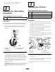
4 Installing the Cutting Units on the Lift Arms Parts needed for this procedure: 4 Thrust washer 4 Clevis pin 2 Hairpin cotter 2 Height-of-cut collar 2 Clevis pin 2 Hairpin cotter 2 Bolt (1/2 x 3/4 inch) 2 Washer Procedure 1. Move the cutting unit into position in front of the traction unit. 2. Move the lift lever to the Float position.
Figure 5 1. PTO shaft 2. Bolts and locknuts 3. Gear case 4. Roll pin 2. Secure them with a roll pin (Figure 5). 3. Tighten the bolts and nuts (Figure 5). 6 Greasing the Machine No Parts Required Procedure Before operating the machine, it must be greased to ensure proper lubricating characteristics; refer to Greasing the Bearings and Bushings. Failure to properly grease the machine will result in premature failure of critical parts.
Product Overview Operation Specifications Note: Determine the left and right sides of the machine from the normal operating position. Note: Specifications and design are subject to change without notice. CAUTION If you leave the key in the ignition switch, someone could accidently start the engine and seriously injure you or other bystanders. Width of 62 inches (1.575 m) or 72 inches (1.
secure the height of cut collar to the desired holes in the height of cut rod. 1. Start the engine and raise the cutting unit off the floor so that the height-of-cut can be changed. Stop the engine and remove the key after the cutting unit is raised. 2. Position the castor wheel axles in the same holes in both castor forks. Refer to Figure 7 & Figure 8 to determine the correct holes for the setting.
Figure 11 2. Jam nut 1. Height-of-cut 7. Rotate the height-of-cut rods to raise or lower the rear of the cutting unit and attain the correct cutting unit pitch. Figure 10 8. Tighten the jam nuts. 7. Secure the adjustment with the clevis pin and hair pin. Adjusting the Skids The skids should be mounted in the lower position when operating in height of cuts greater than 2-1/2 inches (64 mm) and in the higher position when operating in height of cuts lower than 2-1/2 inches (64 mm).
Figure 13 1. Roller 2. Roller shaft Figure 14 1. Tensioning cap 2. Spacers 3. Shims 2. Slide the shaft out of the lower bracket holes, align the roller with the top holes, and install the shaft. 3. Install the screw and nut to secure the assemblies. 4. Axle mounting holes 5.
shredding causes the grass to turn brown at the edges which impairs growth and increases susceptibility to diseases. After Operating To ensure optimum performance, clean the underside of the mower housing after each use. If residue is allowed to build up in the mower housing, cutting performance will decrease. Cutting Unit Pitch We recommend a blade pitch of 1/4 inch (6 mm). A pitch larger than 1/4 inch (6 mm) will result in less power required, larger clippings, and a poorer quality of cut.
Maintenance Recommended Maintenance Schedule(s) Maintenance Service Interval Maintenance Procedure After the first 2 hours • Tighten the castor wheel nuts After the first 10 hours • Tighten the castor wheel nuts • Torque the blade bolts Before each use or daily • Check the blades Every 50 hours • • • • • • Every 400 hours • Change the gear box oil 1 Immediately Lubricate the grease fittings1 Check the gear box oil level Tighten the castor wheel nuts Torque the blade bolts Check the blade drive
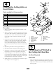
Figure 16 • Idler arm shaft bearings (Figure 16) • Lift arm pivots, front (2) (Figure 17) Figure 19 1. Dipstick/fill plug Separating the Cutting Unit from the Traction Unit 1. Position the machine on level surface, lower the cutting unit to the floor, move the lift lever to the Float position, shut the engine off, and engage the parking brake. Figure 17 2. Remove the bolt and washer mounted to the top of each height of cut rod (Figure 20). • Lift arm pivots, rear (2) (Figure 18) Figure 20 1.
the holes in the castor arm bracket and the height of cut rod can be inserted into the lift arm pads (Figure 23). Figure 21 1. Lift arm 2. Clevis pin 3. Hairpin cotter 4. Castor arm bracket 5. Roll the cutting unit away from the traction unit, separating the male and female sections of the PTO shaft (Figure 22). Figure 22 1. PTO shaft Figure 23 1. 2. 3. 4. 5. 6. DANGER If the engine is started and the PTO shaft is allowed to rotate, serious injury could result.
Servicing the Castor Wheels and Bearings pin cotters (Figure 23). Head of clevis pin to be positioned toward the front of the deck. 10. Install a 1/2 x 3/4 inch bolt and a washer to top of each height of cut rod (Figure 23). 1. Remove the locknut from the bolt holding the castor wheel assembly between the castor fork (Figure 25). Grasp the castor wheel and slide the bolt out of the fork or pivot arm.
Inspecting and Sharpening the Blade(s) G010549 Figure 26 DANGER A worn or damaged blade can break, and a piece of the blade could be thrown into the operator’s or bystander’s area, resulting in serious personal injury or death. 3. Rotate the opposite end of the blade forward. Measure between the cutting unit and cutting edge of the blade at the same position as in step 2 The difference between the dimensions obtained in steps 2 and 3 must not exceed 1/8 inch (3 mm).
Checking and Correcting Mismatch of Blades If there is mismatch between the blades, the grass will appear streaked when it is cut. This problem can be corrected by making sure that the blades are straight and all of the blades are cutting on the same plane. 1. Using a 3 foot (1 meter) long carpenters level, find a level surface on the shop floor. 2. Raise the height-of-cut to the highest position; refer to Adjusting the Height-of-Cut. 3. Lower the cutting unit onto the flat surface.
1. Lower the cutting unit to the shop floor. Remove the belt covers from the top of the cutting unit and set the covers aside. 2. Using a torque wrench or similar tool, move the idler pulley (Figure 30) away from the drive belt to release the belt tension and allow the belt to be slipped off the gearbox pulley (Figure 31). Figure 32 1. Belt routing Figure 30 1. Idler pulley 5. Install the belt covers. Figure 31 1. Gearbox 3. Remove the old belt from around the spindle pulleys and idler pulley. 4.
The Toro Total Coverage Guarantee A Limited Warranty Conditions and Products Covered The Toro® Company and its affiliate, Toro Warranty Company, pursuant to an agreement between them, jointly warrant your Toro Commercial product (“Product”) to be free from defects in materials or workmanship for two years or 1500 operational hours*, whichever occurs first. This warranty is applicable to all products with the exception of Aerators (refer to separate warranty statements for these products).