Form No. 3388-986 Rev A Base 62in and 72in Mower Groundsmaster® 3320/3280-D Traction Unit Model No. 30403—Serial No. 315000001 and Up Model No. 30404—Serial No. 315000001 and Up Register at www.Toro.com.
This manual uses 2 other words to highlight information. Important calls attention to special mechanical information and Note emphasizes general information worthy of special attention. WARNING CALIFORNIA Proposition 65 Warning This product contains a chemical or chemicals known to the State of California to cause cancer, birth defects, or reproductive harm.
Contents Safety Safety ........................................................................... 3 Safe Operating Practices........................................... 3 Toro Mower Safety .................................................. 5 Safety and Instructional Decals ................................. 6 Setup ............................................................................ 8 1 Installing a Completion Kit .................................... 8 2 Installing the Castor Wheel Assemblies .....
Safe Handling of Fuels • Stop equipment and inspect the blades after striking • To avoid personal injury or property damage, use • • • • • • • • • • • extreme care in handling gasoline. Gasoline is extremely flammable and the vapors are explosive. Extinguish all cigarettes, cigars, pipes, and other sources of ignition. Use only an approved fuel container. Never remove fuel cap or add fuel with the engine running. Allow engine to cool before refueling. Never refuel the machine indoors.
Hauling • Make sure that all hydraulic line connectors are tight and all hydraulic hoses and lines are in good condition before applying pressure to the system. • Use care when loading or unloading the machine into a • • trailer or truck. Use full width ramps for loading machine into trailer or truck. Tie the machine down securely using straps, chains, cable, or ropes.
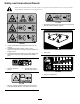
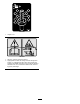
Safety and Instructional Decals Safety decals and instructions are easily visible to the operator and are located near any area of potential danger. Replace any decal that is damaged or lost. 117–4979 1. Entanglement hazard, belt—stay away from moving parts, keep all guards and shields in place. 120-6604 1. Thrown object hazard—keep bystanders away from the machine. 2. Cutting/dismemberment hazard of hand, mower blade—stay away from moving parts, keep all guards and shields in place. 108-1988 1.
108-1986 1. Height of cut 115-4505 1. Warning—read the Operator's Manual. 2. Tipping hazard—lower the cutting unit when driving down slopes. For 2 wheel drive units, add a 16 kg (35 lb) rear weight to GM 3280D units and a 32 kg (70 lb) rear weight to GM 3320 units. For 4 wheel drive 3280 D units, add a 16 kg (35 lb) rear weight.
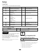
Setup Loose Parts Use the chart below to verify that all parts have been shipped. Procedure Description 1 2 3 4 5 6 Use Qty. Completion kit (sold separately) 1 Install a completion kit. Castor wheel assembly 2 Install the castor wheel assemblies.
2 3 Installing the Castor Wheel Assemblies Installing the Lift Arms Parts needed for this procedure: Parts needed for this procedure: 2 Castor wheel assembly Procedure The thrust washers, spacers, and tensioning caps have been installed on the castor wheel spindles for shipping. 1 Lift arm, right 1 Lift arm, left 2 Pivot pin assembly 2 Cotter pin Procedure 1. On one side of the traction unit, loosen (do not remove) the wheel nuts securing the wheel and tire assembly to the front wheel studs.
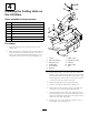
4 Installing the Cutting Units on the Lift Arms Parts needed for this procedure: 4 Thrust washer 4 Clevis pin 2 Hairpin cotter 2 Height-of-cut collar 2 Clevis pin 2 Hairpin cotter 2 Bolt (1/2 x 3/4 inch) 2 Washer Procedure 1. Move the cutting unit into position in front of the traction unit. 2. Move the lift lever to the Float position.
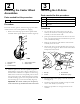
Product Overview 5 Specifications Connecting the PTO Shaft to the Cutting Unit Gear Box Note: Specifications and design are subject to change without notice. No Parts Required Procedure 1. Slide the male PTO shaft into the female PTO shaft (Figure 5). Align the mounting holes in the gear case input shaft with the holes in the PTO shaft and slide them together. Width of Cut 1.575 m (62 inches) or 1.
Operation engine and remove the key after the cutting unit is raised. Note: Determine the left and right sides of the machine from the normal operating position. 2. Position the castor wheel axles in the same holes in both castor forks. Refer to Figure 7 & Figure 8 to determine the correct holes for the setting.
Adjusting the Cutting Unit Pitch 4. Push the castor spindle through the castor arm. Install the shims (as they were originally installed) and the remaining spacers onto the spindle shaft. Install the tensioning cap to secure the assembly. Cutting unit pitch is the difference in height-of-cut from the front of the blade plane to the back of the blade plane. Toro recommends a blade pitch of 6 mm (1/4 inch). That is the back of the blade plane is 6 mm (1/4 inch) higher than the front. 5.
4. Check for bent blades; refer to Checking for a Bent Blade. 5. Cut grass in a test area to determine if all cutting units are cutting at the same height. 6. If cutting unit adjustments are still needed, find a flat surface using a 2 m (6 foot) or longer straight edge. 7. To ease measuring blade plane, raise the height of cut to the highest position; refer to Adjusting the Height of Cut. 8. Lower cutting unit onto the flat surface. Remove the covers from the top of the cutting units. Figure 12 1. Skid 9.
dense grass, you may have to raise the height-of-cut to the next setting. Mow at Proper Intervals Under most normal conditions you will need to mow approximately every 4–5 days. But remember, grass grows at different rates at different times. This means that in order to maintain the same height-of-cut, which is a good practice, you will need to cut more frequently in early spring; as the grass growth rate slows in mid summer, cut only every 8–10 days.
Maintenance Recommended Maintenance Schedule(s) Maintenance Service Interval Maintenance Procedure After the first 2 hours • Tighten the castor wheel nuts After the first 10 hours • Tighten the castor wheel nuts • Torque the blade bolts Before each use or daily 1 • Check the blades Every 50 hours • • • • • • Lubricate the grease fittings 1 Check the gear box oil level Tighten the castor wheel nuts Torque the blade bolts Check the blade drive belt adjustment Clean under the cutting unit belt cover
Figure 16 • Idler arm shaft bearings (Figure 16) • Lift arm pivots, front (2) (Figure 17) Figure 19 1. Dipstick/fill plug Separating the Cutting Unit from the Traction Unit 1. Position the machine on level surface, lower the cutting unit to the floor, move the lift lever to the Float position, shut the engine off, and engage the parking brake. Figure 17 2. Remove the bolt and washer mounted to the top of each height of cut rod (Figure 20).
holes in the castor arm bracket and the height of cut rod can be inserted into the lift arm pads (Figure 23). Figure 21 1. Lift arm 3. Hairpin cotter 2. Clevis pin 4. Castor arm bracket 5. Roll the cutting unit away from the traction unit, separating the male and female sections of the PTO shaft (Figure 22). Figure 22 Figure 23 1. PTO shaft 1. Lift arm DANGER If the engine is started and the PTO shaft is allowed to rotate, serious injury could result.
Servicing the Bushings in the Castor Arms The castor arms have bushings pressed into the top and bottom of the tube and after many hours of operation, the bushings will wear. To check the bushings, move the castor fork back and forth and from side to side. If the castor spindle is loose inside the bushings, the bushings are worn and must be replaced. 1. Raise the cutting unit so that the wheels are off of the floor. Block the cutting unit so that it cannot accidentally fall. 2.
Inspecting and Sharpening the Blade(s) 3 mm (1/8 inch), replace the blade because it is bent; refer to Removing the Cutting Blade. Removing and Installing the Blade(s) DANGER A worn or damaged blade can break, and a piece of the blade could be thrown into the operator's or bystander's area, resulting in serious personal injury or death. • Inspect the blade periodically for wear or damage. • Do not try to straighten a blade that is bent. • Never weld a broken or cracked blade.
forward, and measure again. The difference between the dimensions must not exceed 1 meter (3 foot). If the dimension exceeds 1 meter (3 foot), replace the blade because it is bent. Make sure to measure all of the blades. WARNING If the blade is allowed to wear, a slot will form between the sail and flat part of the blade (Figure 28). Eventually, a piece of the blade may break off and be thrown from under the housing, possibly resulting in serious injury to yourself or bystanders.
Figure 31 1. Gearbox 3. Remove the old belt from around the spindle pulleys and idler pulley. 4. Route the new belt around the spindle pulleys and idler pulley assembly as shown in Figure 32. Figure 32 1. Belt routing 5. Install the belt covers.
Declaration of Incorporation The Toro Company, 8111 Lyndale Ave. South, Bloomington, MN, USA declares that the following unit(s) conform(s) to the directives listed, when installed in accordance with the accompanying instructions onto certain Toro models as indicated on the relevant Declarations of Conformity. Model No. Serial No.
The Toro Total Coverage Guarantee A Limited Warranty Conditions and Products Covered The Toro Company and its affiliate, Toro Warranty Company, pursuant to an agreement between them, jointly warrant your Toro Commercial product (“Product”) to be free from defects in materials or workmanship for two years or 1500 operational hours*, whichever occurs first. This warranty is applicable to all products with the exception of Aerators (refer to separate warranty statements for these products).