Form No. 3425-822 Rev A Base 62in and 72in Mower Groundsmaster® 3320/3280-D Traction Unit Model No. 30403—Serial No. 403330001 and Up Model No. 30404—Serial No. 403330001 and Up Register at www.Toro.com.
This product complies with all relevant European directives. For details, please see the Declaration of Incorporation (DOI) at the back of this publication. WARNING CALIFORNIA Proposition 65 Warning Use of this product may cause exposure to chemicals known to the State of California to cause cancer, birth defects, or other reproductive harm. g243406 Figure 1 Introduction Model No.
Contents Safety Safety ....................................................................... 3 General Safety ................................................... 3 Cutting Unit Safety.............................................. 3 Safety and Instructional Decals .......................... 5 Setup ........................................................................ 7 1 Preparing the Machine..................................... 7 2 Installing a Completion Kit................................
• Keep all parts in good working condition and all hardware tightened. Replace all worn or damaged decals. • Use only accessories, attachments, and replacement parts approved by Toro.
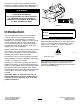
Safety and Instructional Decals Safety decals and instructions are easily visible to the operator and are located near any area of potential danger. Replace any decal that is damaged or missing. decal117-4979 117–4979 1. Entanglement hazard, belt—stay away from moving parts, keep all guards and shields in place. decal120-6604 120-6604 1. Thrown object hazard—keep bystanders away from the machine. 2.
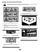
decal108-1986 108-1986 1. Height of cut decal115-4505 115-4505 1. Warning—read the Operator's Manual. 2. Tipping hazard—lower the cutting unit when driving down slopes. For 2 wheel drive units, add a 16 kg (35 lb) rear weight to GM 3280D units and a 32 kg (70 lb) rear weight to GM 3320 units. For 4 wheel drive 3280 D units, add a 16 kg (35 lb) rear weight.
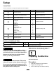
Setup Loose Parts Use the chart below to verify that all parts have been shipped. Procedure Description 1 2 3 4 5 6 7 Use Qty. No parts required – Prepare the machine. Completion kit (sold separately) 1 Install a completion kit. Castor wheel assembly 2 Install the castor wheel assemblies.
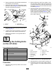
2 Installing a Completion Kit Parts needed for this procedure: 1 Completion kit (sold separately) Procedure Install 1 of the following 62-inch or 72-inch completion kits to the base deck using the instruction provided in the kit: g008866 Figure 3 • Model 30303, 72-inch Rear Discharge • Model 30304, 72-inch Guardian 1. Tensioning cap 4. Axle mounting holes 2. Spacers 5. Castor wheel 3. Thrust washers • Model 30305, 62-inch Rear Discharge 2.
3. Remove the wheel nuts and slide the wheel and tire assembly off of the studs. 4. Mount a lift arm to the pivot bracket with a pivot pin and a cotter pin (Figure 4). Mount the lift arm with the bend positioned outward. 2. Move the lift lever to the FLOAT position. Push a lift arm down until the holes in the lift arm line up with the holes in the castor arm bracket and the height of cut rod can be inserted into the lift arm pads (Figure 5). 3.
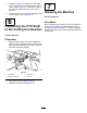
7. Install the height of cut collars onto the height of cut rods and secure with the clevis pins and hairpin cotters (Figure 5). Position the head of the clevis pin toward the front of the deck, if possible. 8. Install a bolt (1/2 x 3/4 inch) and a washer to top of each height of cut rod (Figure 5). 7 Greasing the Machine No Parts Required 6 Procedure Before operating the machine, it must be greased to ensure proper lubricating characteristics; refer to 7 Greasing the Machine (page 10).
Product Overview Operation Specifications Note: Determine the left and right sides of the machine from the normal operating position. Note: Specifications and design are subject to CAUTION change without notice. Width of Cut 1.575 m (62 inches) or 1.829 m (72 inches) Height of Cut Adjustable from 25 to 127 mm (1 to 5 inches) in 13 mm (1/2 inch) increments Net Weight Model 30403–190 kg (420 lbs.) Model 30404–231 kg (510 lbs.
g012231 Figure 9 1. Height-of-cut rod g008866 2. Height-of-cut collar Figure 7 1. Tensioning cap 4. Axle mounting holes 2. Spacers 5. Castor wheel 3. Clevis pin and hairpin cotter 6. 3. Shims Align the height-of-cut collar to the desired height-of-cut holes on the height-of-cut rod (Figure 10). decal100-5622 Figure 8 4. 5. Push the castor spindle through the castor arm. Install the shims (as they were originally installed) and the remaining spacers onto the spindle shaft.
Adjusting the Skids Adjusting the Cutting Unit Pitch Mount the skids in the lower position when operating in height of cuts higher than 64 mm (2-1/2 inches) and in the higher position when operating in height of cuts lower than 64 mm (2-1/2 inches). Cutting unit pitch is the difference in height-of-cut from the front of the blade plane to the back of the blade plane. Use a blade pitch of 6 mm (1/4 inch). That is the back of the blade plane is 6 mm (1/4 inch) higher than the front. 1.
Adjusting the Rollers Note: If the cutting unit is to be used in the 25 or 38 mm (1 or 1-1/2 inch) height-of-cut setting, position the cutting unit rollers in the top bracket holes. 1. Remove the screw and nut securing the roller shaft to the deck bracket (Figure 13). 8. Lower cutting unit onto the flat surface. Remove the covers from the top of the cutting units. 9. Rotate the blade on each spindle until the ends face forward and backward. 10.
Operating Tips inside the cutting unit, cutting quality will eventually become unsatisfactory. Fast Throttle Setting/Ground Speed To reduce the risk of fire hazard, keep the engine, muffler, battery compartment, parking brake, cutting units, and fuel storage compartment free of grass, leaves, or excessive grease. Clean up any spilled oil or fuel. To maintain enough power for the machine and deck while mowing, operate the engine at the fast throttle position and adjust your ground speed for conditions.
Maintenance Note: Determine the left and right sides of the machine from the normal operating position. Recommended Maintenance Schedule(s) Maintenance Service Interval Maintenance Procedure After the first 2 hours • Tighten the castor wheel nuts. After the first 10 hours • Tighten the castor wheel nuts. • Torque the blade bolts. Before each use or daily • • • • Lubricate the castor arm bushings. Lubricate the castor wheel bearings. Check the blades. Clean the cutting unit.
CAUTION If you leave the key in the ignition switch, someone could accidently start the engine and seriously injure you or other bystanders. Remove the key from the ignition before you do any maintenance. Important: The fasteners on the covers of this machine are designed to remain on the cover after removal. Loosen all the fasteners on each cover a few turns so that the cover is loose but still attached, then go back and loosen them until the cover comes free.
2. the rear of the cutting unit (Figure 20). Remove the height of cut collar. Remove the dipstick/fill plug from the top of the gearbox (Figure 19) and ensure that the lubricant is between the marks on the dipstick. If the lubricant level is low, add enough lubricant until the level is between the marks. 4. Remove the hairpin cotters and clevis pins securing the lift arms to the castor arm brackets (Figure 21). g012237 Figure 21 g010548 Figure 19 1. Dipstick/fill plug 1. Lift arm 3.
Mounting the Cutting Unit to the Traction Unit 1. 2. 3. 4. and the castor arm bracket (Figure 23). Insert end of cotter pin into the slot in the castor arm tab to retain cotter pin. Position the machine on a level surface and shut the engine off. Move the cutting unit into position in front of the traction unit. Slide the male PTO shaft into the female PTO shaft (Figure 22). Move the lift lever to the FLOAT position.
5. Apply grease to the inside and outside of the new bushings. Using a hammer and flat plate, drive the bushings into the mounting tube. 6. Inspect the castor spindle for wear and replace it if damaged. 7. Push the castor spindle through the bushings and mounting tube, slide the thrust washer and spacer(s) onto the spindle, and install the tensioning cap on the castor spindle.
1. 2. good quality-of-cut. The sail is important because it pulls grass up straight, thereby producing an even cut. However, the sail will gradually wear down during operation, and this condition is normal. As the sail wears down, the quality-of-cut will degrade somewhat, although the cutting edges are sharp. The cutting edge of the blade must be sharp so that the grass is cut rather than torn. A dull cutting edge is evident when the tips of the grass appear brown and shredded.
where the shims must be added. To raise or lower the blade, add a shim, Part No. 3256-24, between the spindle housing and the bottom of the cutting unit. Continue to check the alignment of the blades and add shims until the tips of the blades are within the required dimension. nicked. Sharpen only the top side of the cutting edge and maintain the original cutting angle to ensure sharpness (Figure 29). The blade will remain balanced if the same amount of metal is removed from both cutting edges.
3. Remove the old belt from around the spindle pulleys and idler pulley. 4. Route the new belt around the spindle pulleys and idler pulley assembly as shown in Figure 32. Storage 1. Disengage the PTO, release the traction pedal to the neutral position, and engage the parking brake. 2. Shut off the engine, remove the key, and wait for all moving parts to stop before leaving the operator’s position. 3. Allow the engine to cool before adjusting, cleaning, storing, or repairing the machine. 4.
Notes:
Declaration of Incorporation The Toro Company, 8111 Lyndale Ave. South, Bloomington, MN, USA declares that the following unit(s) conform(s) to the directives listed, when installed in accordance with the accompanying instructions onto certain Toro models as indicated on the relevant Declarations of Conformity. Model No. Serial No.
California Proposition 65 Warning Information What is this warning? You may see a product for sale that has a warning label like the following: WARNING: Cancer and Reproductive Harm—www.p65Warnings.ca.gov. What is Prop 65? Prop 65 applies to any company operating in California, selling products in California, or manufacturing products that may be sold in or brought into California.
EEA/UK Privacy Notice Toro’s Use of Your Personal Information The Toro Company (“Toro”) respects your privacy. When you purchase our products, we may collect certain personal information about you, either directly from you or through your local Toro company or dealer.
The Toro Warranty A Two-Year Limited Warranty Conditions and Products Covered The Toro Company and its affiliate, Toro Warranty Company, pursuant to an agreement between them, jointly warrant your Toro Commercial product (“Product”) to be free from defects in materials or workmanship for two years or 1500 operational hours*, whichever occurs first. This warranty is applicable to all products with the exception of Aerators (refer to separate warranty statements for these products).