Form No. 3378-131 Rev A Flow Divider Kit Groundsmaster® 4000 Series Traction Unit with Yanmar Engine Model No. 30407 Installation Instructions WARNING CALIFORNIA Proposition 65 Warning This product contains a chemical or chemicals known to the State of California to cause cancer, birth defects, or reproductive harm. Installation Loose Parts Use the chart below to verify that all parts have been shipped. Description Use Qty. No parts required – Prepare the machine.
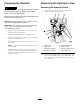
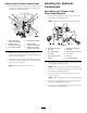
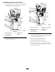
Preparing the Machine Removing the Hydraulic Lines CAUTION Removing the Hydraulic Hoses If you leave the key in the ignition switch, someone could accidently start the engine and seriously injure you or other bystanders. 1. Align a drain pan below the forward end of the hydraulic-pressure hose (Figure 1). 1 2 3 Remove the key from the ignition switch before you perform any maintenance. Important: Use lifting and support equipment with a capacity of 1300 kg (5000 lb) or greater.
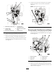
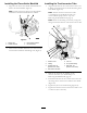
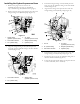
1 2 6. Pull the rear-traction hose through the hose support bracket, and remove the hose from the machine (Figure 3). Note: Discard the rear-traction hose. 3 4 5 1 2 6 G021358 G021357 Figure 3 Figure 2 1. Middle fitting (divider-tube) 4. Forward fitting (rear-traction hose) 2. Forward fitting (pressure-hose) 5. Rear fitting (rear-traction hose) 3. Rear fitting (divider-tube) 6. Bulkhead fitting 7. Temporarily cap the bulkhead fitting. Removing the Tube Bracket and Clamp 1.
Removing the Divider Tube Note: Discard the bolts, nuts, clamp-block halves, and support bracket. 1. Remove the tube nut of the divider tube from the T-fitting in the front-right traction motor, and remove the tube from the machine (Figure 6). 2 1 1 2 3 4 G021361 Figure 6 G021360 1. T-fitting (traction motor) Figure 5 1. Bolts 3. Support bracket 2. Chassis bracket 4. Flange nuts 2. Tube nut (divider tube) Note: Discard the divider tube. 2. Temporarily cap the T-fitting in the traction motor.
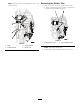
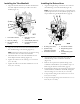
Installing the Hydraulic Components Removing the Traction-control Hose 1. Remove the inboard-hose fitting for the traction-control hose from the hydraulic fitting in port (CH1) of the combination manifold (Figure 7). Assembling the Fittings to the Flow-divider Manifold 3 2 1. Thread the 45° hydraulic fitting into port (P1) of the flow-divider manifold (Figure 8). 4 1 Note: Tighten the jam nut for the fitting hand tight. 2 3 1 4 5 5 6 6 M1 G021362 M3 Figure 7 1 CH 1.
Installing the Traction-motor Tube Installing the Flow-divider Manifold 1. Align the tube nuts for the traction-motor tube to the T-fitting in the traction motor and the 90º fitting in the flow divider (Figure 10). 1. Align the holes in the flow-divider manifold with the holes in the chassis bracket (Figure 9). Note: Ensure that the 45º fitting in the flow-divider manifold is toward the centerline of the machine.
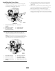
Installing the Return Hose Installing the Tube Manifold 1. Align the straight fitting of the return hose with the threaded fitting of the tube manifold (Figure 12). 1. Align the forward-tube nut for the tube manifold with the check adapter located in port CH1 of the flow divider (Figure 11). Note: Ensure that the return hose is routed above the hydraulic-pressure hose of the hydraulic pump; refer to step 2 of Removing the Hydraulic Hoses (page 2). Figure 11 1. Flow-divider manifold 4.
Installing the Cross Hose 3. Align the straight fitting of the cross hose with the 45° hydraulic fitting in the rear-traction manifold (Figure 14). 1. Align the 90° fitting of the cross hose through the cushioned guide in the support bracket, and slide the hose through the bracket (Figure 13). 4. Remove the cap from the 45° hydraulic fitting in the rear-traction manifold that you installed in step 3 of Removing the Traction-control Hose (page 5). 5.
Installing the Rear-traction Hose 1. Align the fitting of the rear-traction hose through the cushioned guide of the support bracket, and slide the hose through the bracket (Figure 15). Figure 16 Figure 15 1. Rear-traction hose 4. Bulkhead fitting 2. Cushioned guide 5. Bulkhead 1. Flow-divider manifold 4. Rear fitting (rear-traction hose) 2. Straight-hydraulic fitting 5. Bulkhead fitting 3. Forward fitting (rear-traction hose) 6. Bulkhead 3.
Installing the Hydraulic-pressure Hose 4. Thread the straight fitting of the hydraulic-pressure hose onto the 45° hydraulic fitting in the flow-divider manifold (Figure 18). 1. Remove the plug from the end of the hydraulic-pressure hose that you installed in step 3 of Removing the Hydraulic Hoses (page 2). 5. Align the 45° fitting of the pressure hose with the straight fitting in the hydraulic pump (Figure 19). 2.
Checking for Hydraulic Leaks Operation WARNING Operating Tips Hydraulic fluid escaping under pressure can penetrate skin and cause injury. The flow divider kit enhances the traction drive performance in compromised operating conditions. • Make sure that all hydraulic fluid hoses and lines are in good condition and all hydraulic connections and fittings are tight before applying pressure to the hydraulic system.
2.75 CID .0315 250 psi P4 .0315 CH2 12 5000 psi 4350 PSI CH1 30.5 GPM CV2 HFD Split 43-57 CV1 Hydraulic Schematic (Rev. A) T .050 OR1 P2 FRONT TRACTION AL V VE REAR TRACTION VALVE P1 P3 380 psi CV CH2 PR OR .063 CH3 CH1 G3 650 psi M3 M1 M8 RV CH OR9 200 psi 13.1 GPM 17.4 GPM T 2.14 CID / 1.16 CID 2SP 1.4 CID / 0.79 CID 1.4 CID / 0.