
Installation Instructions

RemovingtheTraction-controlHose
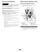
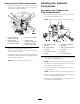
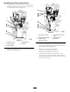
1.Removetheinboard-hosettingforthetraction-control
hosefromthehydraulicttinginport(CH1)ofthe
combinationmanifold(Figure7).
G021362
1
2
3
4
5
6
Figure7
1.Inboard-hosetting
(traction-controlhose)
4.Rear-tractionmanifold
2.Hydraulictting
(combinationmanifold)
5.Hydraulictting
(rear-tractionmanifold)
3.Combinationmanifold6.Outboard-hosetting
(traction-controlhose)
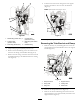
2.Removetheoutboard-hosettingforthe
traction-controlhosefromthe45°hydraulicttingin
therear-tractionmanifold.
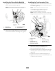
3.Temporarilycapthestraight-hydraulicttingsinthe
combinationmanifoldandthe45°hydraulicttingin
therear-tractionmanifold.
Note:Discardthetraction-controlhose.
InstallingtheHydraulic
Components
AssemblingtheFittingstothe
Flow-dividerManifold
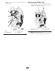
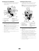
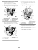
1.Threadthe45°hydraulicttingintoport(P1)ofthe
ow-dividermanifold(Figure8).
Note:Tightenthejamnutforthettinghandtight.
M1
M3
CH1
G021369
1 2
3
4
5
7
8
9101112
6
Figure8
1.Flow-dividermanifold7.Straight-hydraulictting
2.Port(M1)8.Port(M3)
3.90°hydraulictting9.Checkadapter(9/16inch)
4.Port(CH2)10.Port(CH1)
5.Checktting(3/4inch)11.Port(P1)
6.T-tting12.45°hydraulictting
2.Threadthe90°hydraulicttingintoport(M1)ofthe
ow-dividermanifold(Figure8).
Note:Tightenthejamnutforthettinghandtight.
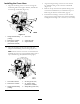
3.Installthe3/4inchcheckttingintoport(CH2)ofthe
ow-dividermanifold(Figure8).
4.ThreadthetubenutoftheT-ttingontothecheck
tting(
Figure8).
Note:TightenthetubenutoftheT-ttinghandtight.
5.Installthestraight-hydraulicttingintoport(M3)of
theow-dividermanifold(
Figure8).
6.Installthe9/16checkadapterintoport(CH1)ofthe
ow-dividermanifold(Figure8).
5