
Installation Instructions

InstallingtheTubeManifold
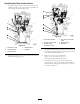
1.Aligntheforward-tubenutforthetubemanifoldwith
thecheckadapterlocatedinportCH1oftheow
divider(Figure11).
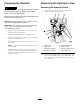
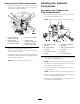
Figure11
1.Flow-dividermanifold4.Rear-tubenut(tube
manifold)
2.Tubenut(T-tting)5.Checkadapter(9/16inch)
3.90°threadedtting
(T-tting)
6.Forward-tubenut(tube
manifold)
2.Aligntherear-tubenutforthetubemanifoldwiththe
90°threadedttingoftheT-tting(Figure11).
Note:RotatetheT-ttingnecessarytoalignthetting
withtherear-tubenutofthetubemanifold.
3.Threadthetubenutsofthetubemanifoldontothe
checkadapterandtheT-tting(Figure11).
4.TightenthetubenutoftheT-ttingto51to63N-m
(37to47ft-lb).
5.Tightenthetubenutofthetubemanifoldto51to63
N-m(37to47ft-lb).
InstallingtheReturnHose
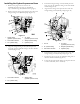
1.Alignthestraightttingofthereturnhosewiththe
threadedttingofthetubemanifold(Figure12).
Note:Ensurethatthereturnhoseisroutedabovethe
hydraulic-pressurehoseofthehydraulicpump;referto
step2ofRemovingtheHydraulicHoses(page2).
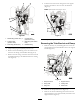
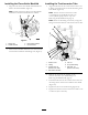
Figure12
1.90ºtting(returnhose)4.Flow-dividermanifold
2.Hydraulictting
(combinationmanifold)
5.Straighttting(return
hose)
3.Combinationmanifold6.Threadedtting(tube
manifold)
2.Alignthe90°ttingofthereturnhosewiththe
threadedttinginthecombinationmanifold
(Figure12).
3.Removethecapfromthehydraulicttinginthe
combinationmanifoldthatyouinstalledinstep3of
RemovingtheTraction-controlHose(page5).
4.Threadthehosettingsontothettingsofthereturn
manifoldandthecombinationmanifold,andtighten
thehosettingsto51to63N-m(37to47ft-lb).
5.Torquethe90°ttingofthereturnhoseto51to63
N-m(37to47ft-lb).
6.Torquethestraightttingofthereturnhoseto37to
44N-m(27to33ft-lb).
7