Form No. 3437-261 Rev A North American Light Kit Groundsmaster® 4000 Series Traction Unit with Yanmar Engine Model No. 30414 Installation Instructions Installation Loose Parts Use the chart below to verify that all parts have been shipped. Procedure 1 2 3 4 5 6 7 8 © 2019—The Toro® Company 8111 Lyndale Avenue South Bloomington, MN 55420 Description Use Qty.
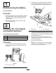
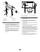
. 1 Install the turn signal switch into the lower hole in of the steering tower dash panel (Figure 2). The turn signal switch is an On-Off-On switch. Disconnecting the Battery No Parts Required Procedure 1. Position the machine on a level surface, engage the parking brake, lower the cutting units, turn the ignition off, and remove the key from the ignition switch. 2. Disconnect the black negative battery cable from the battery post.
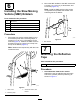
Installing the Headlights Parts needed for this procedure: 2 Headlight bracket 2 Headlight assembly 2 Tie clip 2 Short wire harness Procedure 1. Remove the 2 bolts, washers and nuts from the front of the operator's platform (Figure 3). g309693 Figure 4 g021734 Figure 3 1. Bolt, washer and nut 1. Headlight assembly 4. Hardware with the headlight assembly 2. Short wire harness 5. Headlight bracket 3. Existing hardware with the machine 2.
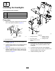
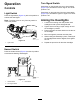
5. Locate the wire harness under the control panel. Plug the wire harness connector labeled “lights” into the switch. 6. Install the cover and plate to the right side of the control arm. Installing the Light Switch 5 Parts needed for this procedure: 1 Light switch Installing the Tail Light Assemblies Procedure 1. Remove the 2 screws that secure the plate to the right cover of the control arm (Figure 5).
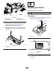
g022329 Figure 8 1. 30 cm (12.00 inches) 3. 46 cm (18.25 inches) 2. 39 cm (15.50 inches) g022345 Figure 7 1. Cable tie 5. Right tail light 2. Mounting pad 6. Tie clip 3. Wire harness 7. Left tail light 4. Tighten the U-bolt nuts evenly to avoid distorting the light mounts. 5. Locate the cab harness connector in the machine platform harness and remove the connector cap. 6. Plug the enclosed tail light wire harness into the cab connector. 7.
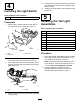
2. 6 Mount the SMV emblem to the SMV mount with 2 screws (1/4 x 3/4 inch), 2 flat washers, and 2 locknuts (Figure 10). Note: Install the SMV emblem using a hole configuration that prohibits the emblem from extending above the ROPS. Installing the Slow Moving Vehicle (SMV) Emblem Parts needed for this procedure: 1 SMV mount 2 Mounting strap 4 Screw (1/4 x 1/2 inch) 2 Flat washers 4 Locknuts Procedure 1.
8 Installing the Fuses Parts needed for this procedure: 2 Procedure g022346 Figure 11 1. Reflective tape, Groundsmaster 4000 1. 2. Reflective tape, Groundsmaster 4100 2. Groundsmaster 4100 Series models only–Affix a strip of reflective tape onto each side of the frame, below the ROPS post, positioning as shown in Figure 11. 3. All models–Affix a strip of reflective tape onto each end of the bumper positioning as shown in Figure 12.
Turn Signal Switch Operation Press down on the left side of the turn signal switch (Figure 16) to activate the left turn signal. The center position is off. Controls Press down on the right side of the turn signal switch (Figure 16) to activate the right turn signal. The center position is off. Light Switch Press the light switch (Figure 15) to the ON position to activate the head lights. Aiming the Headlights Note: The lights come on only if the key switch is in the RUN position. 1.