Form No. 3326–246 Rev B Debris Blower Groundsmaster) 4000–D Model No. 30425—Serial No.
Contents Introduction . . . . . . . . . . . . . . . . . . . . . . . . . . . . . . . . . Safety . . . . . . . . . . . . . . . . . . . . . . . . . . . . . . . . . . . . . . Before Operating . . . . . . . . . . . . . . . . . . . . . . . . . . While Operating . . . . . . . . . . . . . . . . . . . . . . . . . . . Maintenance . . . . . . . . . . . . . . . . . . . . . . . . . . . . . . Sound Pressure Level . . . . . . . . . . . . . . . . . . . . . . . Sound Power Level . . . . . . . . . . . . . . . . . . . . . . .
Safety which may cause a roll over. Use extra caution when operating a traction unit with a blower attached in place of mowing decks. Hazard control and accident prevention are dependent upon the awareness, concern, and proper training of the personnel involved in the operation, transport, maintenance, and storage of the machine. Improper use or maintenance of the machine can result in injury or death. To reduce the potential for injury or death, comply with the following safety instructions.
• Be sure that the machine is in safe operating condition by keeping nuts, bolts, and screws tight. Check all bolts and nuts frequently to be sure that they are tightened to specification. • To ensure optimum performance and safety, always purchase genuine Toro replacement parts and accessories to keep the machine all Toro. Never use “will-fit” replacement parts and accessories made by other manufacturers. Look for the Toro logo to ensure genuineness.
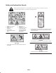
Safety and Instruction Decals Safety decals and instructions are easily visible to the operator and are located near any area of potential danger. Replace any decal that is damaged or lost. 98-3110 1. Danger–See Operator’s Manual 2. Danger–Wear ear protection 3. Thrown object hazard–Keep bystanders away. 4. Always wear eye protection 5. Cutting hazard to hands or feet–wait until all machine components have stopped before touching them. 105-4593 1.
Specifications General Specifications Fan Output 5000 CFM 165 MPH Fan Speed 2575 RPM Outlet Area Adjustable outlet opening, 39 to 70 square inches Directional Control Castor Wheels Height Adjustment 90 degree outlet deflector operated from seat Two 8 x 3–1/2 inch solid rubber tires 4 to 6–1/2 inches Adjustment is with 1/2 inch spacers and holes in castor fork Ground Clearance–Transport 11–1/4 inches Fan Fan Housing Drive Weight: Backward curved, cast aluminium fan.
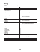
Setup Note: Use this chart as a checklist to ensure that all parts have been received. Without these parts, total setup cannot be completed. Description Qty. Use Blower Housing Assembly 1 Arm Assembly – R.H. 1 Arm Assembly – L.H.
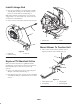
Note: Determine the left and right sides of the machine from the normal operating position. 4. Remove hair pin cotters and clevis pins securing height-of-cut chains to rear of deck (Fig. 3). Retain hair pin cotters and clevis pins for re–installation of front deck Remove Front Cutting Unit 1. Position machine on a level surface, lower mower decks to the floor, engage parking brake, be sure traction pedal is in neutral position, PTO lever in OFF position, shut engine OFF and remove key from switch. 1 2.
Mount Arm Assemblies 1. Align the rear set of mounting holes in each lift arm with holes in the blower housing mounting brackets. Position lift arms as shown in figure 5. 1 2. Loosely secure each lift arm to mounting bracket with (2) capscrews, flatwashers and locknuts. Do not tighten locknuts. Figure 6 1. Bumper assembly Install Handle Assembly 1. Position handle mounting tube between tabs on top of blower housing (Fig. 7).
Install Linkage Rod 1 1. Insert front end of linkage rod through hole in handle assembly while hooking rear end of linkage rod thru hole in rear tab on deflector assembly (Fig. 8). Note: When mounting a debris blower on a traction unit equipped with a cab, rotate handle 180_ and use front tab on deflector for rod installation. 2. Secure each end of rod with a flatwasher and cotter pin. 2 1 2 Figure 9 1. Manifold block 2. Orifice 3 Mount Blower To Traction Unit 1.
2. Mount each lift arm ball joint mount to each side of blower arm assembly with (2) capscrews (4) flatwashers and (2) locknuts. Position fasteners as shown in figure 10. 2 3. Mount each lift arm to top of each blower arm assembly with (2) capscrews (2) flatwashers, clamping plate, reinforcing plate and (2) locknuts. Position components as shown in figure 10. 3 1 4. Tighten all blower and lift arm mounting fasteners. 2 Install Hydraulic Motor To Blower Figure 12 1. Hydraulic motor 2. Large hoses 1.
Operation 6. Secure hydraulic hoses to blower housing with wire tie (Fig. 14). Note: Determine the left and right sides of the machine from the normal operating position. Operating Tips 2 Warning Discharged air has considerable force and could cause injury or loss of footing. 1 • Stay away from the discharge opening when the machine is operating. • Keep bystanders away from the discharge opening when the machine is running. 1. Practice blowing material.
1 3 2 3 3 2 1 Figure 16 Figure 15 1. Locking cap 2. Spacers 1. Discharge opening deflector screw 2. Discharge direction deflector 3. Thrust washers Adjust Discharge Opening 3. Handle assembly Adjust Discharge Direction The discharge opening (Fig. 16) is adjustable to increase or decrease air output velocity and volume. Decreasing discharge opening size will increase velocity. Lower deflector assembly in front of discharge opening to change from side discharge to front discharge (Fig. 16). 1.
Maintenance Note: Determine the left and right sides of the machine from the normal operating position. Greasing the Blower 1 The debris blower must be lubricated regularly. If machine is operated under normal conditions, lubricate castor and fan bearings and bushings with No. 2 general purpose lithium base grease or molybdenum base grease, after every 8 hours of operation or daily, whichever comes first. Lubricate fittings immediately after every washing, regardless of the interval listed.
4. Insert pin punch into top or bottom of bumper and drive bushing out of tube (Fig. 19). Also drive other bushing out of bumper. Clean inside of bumper to remove any dirt. 1 2 1 2 1 2 Figure 20 1. Outer bearing Figure 19 1. Bumper 2. Inner bearing 2. Bushing Alignment Tool 5. Apply grease to inside and outside of new bushings. Using a hammer and flat plate, drive bushings into bumper. If motor mount components are ever disassembled and have to be realigned, proceed as follows: 6.
The Toro General Commercial Products Warranty A Two-Year Limited Warranty Conditions and Products Covered The Toro Company and its affiliate, Toro Warranty Company, pursuant to an agreement between them, jointly warrant your Toro Commercial Product (“Product”) to be free from defects in materials or workmanship for two years or 1500 operational hours*, whichever occurs first.