Form No. 3365-151 Rev A Rotary Broom Groundsmaster® 4000-D and 4100-D Model No. 30426—Serial No. 310000001 and Up To register your product or download an Operator's Manual or Parts Catalog at no charge, go to www.Toro.com.
Contents Introduction Introduction................................................................. 2 Safety ........................................................................... 3 Before Operating ................................................. 3 While Operating................................................... 3 Maintenance......................................................... 3 Safety and Instructional Decals ............................. 4 Setup.............................................
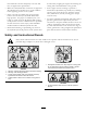
Safety Hazard control and accident prevention are dependent upon the awareness, concern, and proper training of the personnel involved in the operation, transport, maintenance, and storage of the machine. Improper use or maintenance of the machine can result in injury or death. To reduce the potential for injury or death, comply with the following safety instructions. • Before Operating • Read and understand the contents of this Operator’s Manual before operating the machine.
Check all bolts and nuts frequently to be sure that they are tightened to specification. • Make sure all hydraulic line connectors are tight and all hydraulic hoses and lines are in good condition before applying pressure to the system. • Keep your body and hands away from pin hole leaks or nozzles that eject hydraulic fluid under high pressure. Use paper or cardboard, not your hands, to search for leaks.
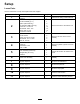
Setup Loose Parts Use the chart below to verify that all parts have been shipped. Procedure 1 2 3 4 5 6 7 8 9 10 11 Description Qty. Use Wire harness cap Cable tie Lift arm assembly (R.H.) Lift arm assembly (L.H.) Spacer (GM 4100 only) Pin assembly (GM 4100 only) Screw 3/8 x 1–1/4 inch Flat washer .406 x .813 Flange lock nut 3/8 Connection channel Spacer Thrust washer Screw, 3/4 x 6–1/2 inches Flat washer, .813 x 1.500 Jam nut, 3/4 inch Flat washer 1.063 x 2.
Media and Additional Parts Description Qty. Use 7 4 6 4 1 1 1 Plug unused hydraulic hoses & ports.Review the material and save in an appropriate place. ORS plug w/ O-ring (–6) ORS plug w/ O-ring (–12) Cap plug w/ O-ring (–6) Cap plug w/ O-ring (–12) Operator’s Manual Parts Catalog Declaration of Conformity Note: Determine the left and right sides of the machine from the normal operating position.
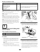
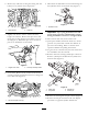
6. Remove any cable ties securing the cutting unit wire harness to any traction unit components. 9. Disconnect the hydraulic hoses from the fittings on the hydraulic motor (center deck only) (Figure 7). Figure 7 1. Hydraulic motor Figure 4 1. Wire harness 2. Cable tie Important: Cap or plug hydraulic hoses and motor ports to prevent contaminating system during installation of broom or storage of deck. 7. Slightly raise deck to remove tension from the height-of-cut chains.
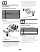
3. Repeat procedure on opposite side of machine. 2 4. Secure right and left lift arms together with the connection channel and (10) 3/8 x 1–1/4 inch screws, .406 x .813 flatwashers and 3/8 flange locknuts. Position as shown in figure Figure 10. Torque the nuts to 27–33 ft–lb. Attaching the Lift Arms to the Traction Unit Parts needed for this procedure: 1 Lift arm assembly (R.H.) 1 Lift arm assembly (L.H.
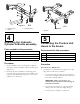
Figure 11 1. Left broom arm 2. Spacer 3. Thrust washers Figure 12 1. Cylinder 4 5 Attaching the Hydraulic Cylinder to Broom assembly Connecting the Traction Unit Hoses to the broom Parts needed for this procedure: 1 Flat washer 1.063 x 2.000 1 Cotter pin 1 Screw M6–1 x 60 1 Lock nut M6 Parts needed for this procedure: Procedure 1 Hose assembly (extension) 1 Hose assembly (extension) 1 Straight fitting w/ O–ring 4 Cable tie Procedure 1.
Figure 14 GM 4000–D Shown 1. Bulkhead 2. Hose w/90 degree fitting 3. Hose w/straight fitting Important: Make sure O–rings are lubricated and in position when making all hydraulic connections. • Connect hose with straight fitting to top bulkhead fitting. • Torque hoses to 43–48 ft.-lb. • Plug small hose with O–ring and plug. Torque to 24–29 ft–lb. Figure 13 GM 4100–D Shown 1. Extension hose w/90 degree fitting 2. Straight adapter 4. Small hose 5. Plug w/O–ring 3.
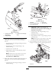
Note: Hoses must not contact sharp edges or moving parts and must be free of twists. Also, make sure the right broom lift arm does not contact the deck sensor. 6 Figure 17 Installing the Chain Cover to the Broom Assembly 1. Counterbalance adjusting screw Important: Whenever rotary broom is removed, make sure to readjust the counterbalance pressure to it’s original setting. Parts needed for this procedure: 1 Chain cover assembly Models 30446, 30447, 30448 and 30449 Procedure 1.
into the lift control valve and readjust the lift relief pressure to it’s original setting (1500 to 1600 psi). 8 Adjusting the Lift Pressure Models 30446, 30447, 30448 and 30449 No Parts Required 1. Stop the engine and remove the key from the ignition. Models 30410 and 30412 2. Remove the cover on the right side of the platform, under the control arm, to access the manifold. 1.
11 Checking the Castor Wheel Tire Pressure No Parts Required Procedure Castor wheel tires to be inflated to 50 psi. Important: Before the rotary broom is operated, it must be greased to assure proper lubricating characteristics: refer to Lubrication section of manual. Failure to properly grease the unit will result in premature failure of critical parts.
Product Overview Specifications Broom Filament Material Virgin polypropylene, high carbon wire or combination of both. Broom Diameter Uses 24 inch broom elements. Oscillation Angle 8 degrees. Sweeping Width Angle Broom swings 25 degrees in both directions. 70.5 inches sweeping width at center position, 64 inches minimum sweeping width at full swing left or right. Castor Wheels Two 8.0 inch x 3.
Adjust Broom Down Pressure Ground Speed Improper downward pressure can decrease broom life up to 95% (depending on the incorrect amount of pressure). Bulldozing produces a side thrust and excessive stress on the broom, core and frame. While operating under the plow effect, the bristles are flexed against the steel ring which holds them and, eventually, this flexing will break the bristles from the ring. A broom sweeps with the tips of its bristles.
Maintenance The rotary broom has (12) fittings that must be lubricated (Figure 22). Note: Determine the left and right sides of the machine from the normal operating position. • Castor shaft bushings (2) Lubrication • Right and left lift arms (2) • Axle shaft bearings (2) • Right and left broom arms (4) The rotary broom must be lubricated regularly. If machine is operated under normal conditions, lubricate bearings and bushings with No.
Adjusting Chain Tension Changing Broom Elements Make sure chain is properly tensioned to assure proper operation of the machine and unnecessary wear. Check chain tension by pressing side of chain at mid span of drive sprockets with 10 lbs. of force. Chain should deflect .10 in. in each direction from center (.20 in. total deflection from side to side). The axle assembly contains 32 broom elements. Summer use: Polypropylene elements. Winter use: Alternating Polypropylene and steel elements (16 ea.). 1.
To check the bushings, move castor fork fore and aft and from side to side. If castor spindle is loose in the bushings, the bushings are worn and must be replaced. 2. Remove locking cap, thrust washers and spacers from top of castor spindle 3. Pull castor spindle out of bumper. Allow thrust washers and spacers to remain on bottom of spindle. 4. Insert pin punch into top or bottom of bumper and drive bushing out of tube (Figure 26). Also drive other bushing out of bumper.
Schematics Hydraulic Schematic (Models 30410 and 30411) (Rev.
Hydraulic Schematic (Models 30412, 30413, 30446, 30447, 30448 and 30449) (Rev.
Electrical Schematic (Models 30410, 30411, 30412 and 30413) (Rev. -) Electrical Schematic (Models 30446, 30447, 30448 and 30449) (Rev.
Notes: 22
Notes: 23
The Toro Total Coverage Guarantee A Limited Warranty Conditions and Products Covered The Toro® Company and its affiliate, Toro Warranty Company, pursuant to an agreement between them, jointly warrant your Toro Commercial product (“Product”) to be free from defects in materials or workmanship for two years or 1500 operational hours*, whichever occurs first. This warranty is applicable to all products with the exception of Aerators (refer to separate warranty statements for these products).