Form No. 3354–528 Rev B Rotary Brush Groundsmaster) 4000–D & 4100–D Model No. 30426—Serial No.
Contents Introduction . . . . . . . . . . . . . . . . . . . . . . . . . . . . . . . . . Safety . . . . . . . . . . . . . . . . . . . . . . . . . . . . . . . . . . . . . . Before Operating . . . . . . . . . . . . . . . . . . . . . . . . . . While Operating . . . . . . . . . . . . . . . . . . . . . . . . . . . Maintenance . . . . . . . . . . . . . . . . . . . . . . . . . . . . . . Sound Pressure Level . . . . . . . . . . . . . . . . . . . . . . . Sound Power Level . . . . . . . . . . . . . . . . . . . . . . .
Before Operating – Do not drive close to a sand trap, ditch, creek, or other hazard. • Read and understand the contents of this Operator’s Manual before operating the machine. Become familiar with all of the controls and know how to stop quickly. A free replacement manual is available by sending the complete Model and Serial Number to The Toro Company, 8111 Lyndale Avenue South, Bloomington, Minnesota 55420-1196. – Reduce your speed when making sharp turns and when turning on hillsides.
Sound Power Level • Before disconnecting or performing any work on the hydraulic system, all pressure in the system must be relieved by stopping the engine and lowering the cutting units and attachments to the ground. This unit has a guaranteed sound power level of 104 dBA/1 pW, based on measurements of identical machines per Directive 2000/14/EC and amendments.
Specifications General Specifications Brush Filament Material Virgin polypropylene, high carbon wire or combination of both. Brush Diameter Uses 24 inch brush elements. Oscillation Angle 8 degrees. Sweeping Width Angle Castor Wheels Ground Clearance Brush Speed Brush Ground Pressure Adjustment Brush swings 25 degrees in both directions. 70.5 inches sweeping width @ center position, 64 inches minimum sweeping width @ full swing left or right. Two 8.0 inch x 3.
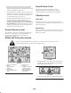
Setup Note: Use this chart as a checklist to ensure that all parts have been received. Without these parts, total setup cannot be completed. Description Qty. Use Lift arm assembly (R.H. & L.H.) 2 Spacer (GM 4100 only) 2 Pin assembly (GM 4100 only) 2 Screw 3/8 x 1–1/4” lg. 10 Flat washer .406 x .813 10 Flange lock nut 3/8 10 Connection channel 1 Spacer 2 Thrust washer 4 Screw 3/4 x 6–1/2” lg. 2 Flat washer .813 x 1.500 2 Jam nut 3/4 2 Flat washer 1.063 x 2.
Note: Determine the left and right sides of the machine from the normal operating position. Note: Implements are heavy and may require two people to handle. Note: Install the rotary brush in a clean work area; cleanliness is extremely important. Before disconnecting the hydraulic lines, thoroughly clean the port areas. After disconnecting hydraulic lines, plug ports and cap lines 2 Remove Front Cutting Unit and Lift Arms 1.
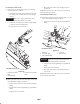
7. Slightly raise deck to remove tension from the height-of-cut chains. Remove hair pin cotters and clevis pins securing height-of-cut chains to rear of deck (Fig. 4). Retain hair pin cotters and clevis pins for re–installation of front deck Important Cap or plug hydraulic hoses and motor ports to prevent contaminating system during installation of brush or storage of deck. 10. Move mower deck away from traction unit. 11. Jack up the machine until front wheels are off the ground.
Mount Brush Assembly 5. Secure left brush arm to left lift arm with a 3/4 x 6–1/2” lg. screw, spacer, (2) thrust washers, .813 x 1.500 flatwasher and 3/4 jam nut (Fig. 10). Thrust washers to be positioned between brush arm bushings and inside of lift arm. Torque to 145–190 ft–lb. 1. Mount left lift arm assembly to frame with lift arm pin and nut previously removed (Fig. 8). Torque to 60–70 ft–lb. 6. Repeat procedure on opposite brush arm. 2 3 3 2 1 4 1 5 Figure 8 1. Left lift arm 2.
• Plug small hose with O–ring and plug. Torque to 24–29 ft–lb. Groundsmaster 4100–D only 9. Connect the (2) extension hoses (Fig. 12) to the large traction unit hoses as follows: Note: Route hoses so they slide on top of the formed rod when operating rotary brush. • Connect the 90_ fitting of the extension hose to the 90_ fitting on the traction unit hose with a straight adapter. Groundsmaster 4000–D only 11. Route and connect the traction unit hoses (Fig.
Adjust Counterbalance 12. Secure hydraulic hoses with (4) wire ties as shown in figure 14. Space wire ties along length of hoses. (Groundsmaster 4100–D only) Reduce counterbalance by unscrewing the stem on the valve approximately 3 turns. Important Whenever rotary brush is removed, make sure to readjust the counterbalance pressure to it’s original setting. 1 Adjust Lift Pressure (Groundsmaster 4000–D only) • Remove the jam nut securing the plug assembly in the lift control valve (Fig.
Adjust Drop Speed Refer to Adjusting the Cutting Unit Flow Control in Traction Unit Operator’s Manual. Check Chain Tension New chains will stretch during the first few days of operation, therefore; check chain tension frequently. If chain requires adjustment, refer to Adjusting Chain. Check Castor Wheel Tire Pressure Castor wheel tires to be inflated to 50 psi.
Operation Adjust castor height for proper brush ground pressure. The castor wheel height is adjustable from 4 to 7 inches in 1/2 inch increments by adding or removing an equal amount of spacers from each castor wheel. Note: Determine the left and right sides of the machine from the normal operating position. 1. Start engine and raise brush. Stop engine after brush is raised. Warning 2. Remove cap securing castor spindle to frame bracket. Thrown debris has considerable force and could cause injury.
Maintenance The rotary brush has (12) fittings that must be lubricated (Fig. 19). Note: Determine the left and right sides of the machine from the normal operating position. • Castor shaft bushings (2) Greasing the Brush • Right and left lift arms (2) • Axle shaft bearings (2) • Right and left brush arms (4) The rotary brush must be lubricated regularly. If machine is operated under normal conditions, lubricate bearings and bushings with No.
Adjusting Chain Tension • Rotate motor until desired chain tension is attained, then tighten nuts. Make sure chain is properly tensioned to assure proper operation of the machine and unnecessary wear. Check chain tension by pressing side of chain at mid span of drive sprockets with 10 lbs. of force. Chain should deflect .10 in. in each direction from center (.20 in. total deflection from side to side). 3. Install chain cover Changing Brush Elements The axle assembly contains 32 brush elements. 1.
Servicing Bumper Bushings Servicing Castor Wheel And Bearing After many hours of operation, the bushings pressed into the top and bottom of the bumper will wear. To check the bushings, move castor fork fore and aft and from side to side. If castor spindle is loose in the bushings, bushings are worn and must be replaced. The castor wheel rotates on a high–quality roller bearing and is supported by a spanner bushing. Even after many hours of use the bearing wear will be minimal.
Hydraulic Schematic T C2 2” BORE 15” STROKE .060 OR P C1 S1 G MP 6.10 P1 R1BY 3000 PSI R1BR 600 PSI ROTARY BRUSH MOTOR BY1 SV1 BR1 MR P2 OR1 .063 CD G MP P1 R1BY 3000 PSI R1BR 600 PSI BY1 1.17 LH DECK MOTOR SV1 BR1 MR 14 GPM P2 14 GPM OR1 .063 CD PROPORTIONAL FLOW DIVIDER G MP R1BR 600 PSI .58 1.2 1.2 P1 R1BY B 2000 PSI BY1 1.17 RH DECK MOTOR P2 CD T 5 PSI SV1 MR RV BR1 250 PSI P2 OR1 .
Electrical Schematic 18
The Toro General Commercial Products Warranty A Two-Year Limited Warranty Conditions and Products Covered The Toro Company and its affiliate, Toro Warranty Company, pursuant to an agreement between them, jointly warrant your Toro Commercial Product (“Product”) to be free from defects in materials or workmanship for two years or 1500 operational hours*, whichever occurs first.