
Installation Instructions


1
All Rights Reserved
Printed in the USA
W 2003 by The Toro Company
8111 Lyndale Avenue South
Bloomington, MN 55420-1196
Flow Divider Kit
Groundsmaster
)
4000-D/4100-D
Model No. 30429
Form No. 3350–246 Rev B
Installation Instructions
1. Engage the parking brake, be sure the traction pedal is
in the neutral position, the PTO lever is in the OFF
position, shut the engine OFF and remove the key from
the switch.
If you leave the key in the ignition switch, someone
could accidently start the engine and seriously
injure you or other bystanders.
Remove the key from the ignition switch before
you do any maintenance.
Caution
2. Raise the machine on a hoist or jack up the front of the
machine. Use jack stands or block the machine to
prevent if from falling.
Important Cap or plug any disconnected hydraulic
hoses, tubes or component ports to prevent contamination
of the system during installation of the kit.
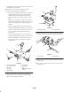
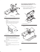
3. Disconnect the hydraulic tube from the tee fitting on the
front of the left wheel motor and from the rear traction
tube (Fig. 1). Remove and retain the quick fitting and
dust cap from the tube (Fig. 1). Discard the tube.
4. Disconnect the hydraulic hose from the 90_ fitting on
the right side of the left wheel motor (Fig. 1). Do not
disconnect the rear end of the hose.
1
3
4
5
6
2
Figure 1
1. Left wheel motor
2. Hydraulic tube
3. Hydraulic hose
4. 90_ Fitting
5. Quick fitting
6. Dust cap
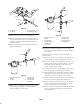
5. Install the quick fitting and the dust cap into the new
hydraulic tube (Fig. 2). Torque the fitting to 15–17
ft–lbs.
6. Loosely connect the hydraulic tube to the rear traction
tube (Fig. 2). Do not tighten at this time.
2
3
1
4
Figure 2
1. New hydraulic tube
2. Quick fitting
3. Dust cap
4. Rear traction tube
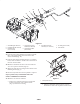
7. Remove and retain the 90_ fitting from the right side of
the left wheel motor.
8. Install the hollow plug w/o–ring into the wheel motor
port were the 90_ fitting was removed (Fig. 3). Torque
the plug to 202–218 ft–lbs.
1
Figure 3
1. Plug w/O–ring