
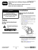
Installation Instructions


edgeat2locationsasindicatedinFigure5.
Rimandpaintirregularitiesmaketheouter
edgeanunreliablepointofmeasure.These
2measurementsshouldbewithin3mm
(1/8inch)ofeachother.
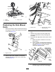
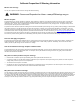
D.Ifthedeckisnotalignedwiththetraction
unit,loosenthejamnutontherodendof
thewing-deckshock-armassembly(Figure
6).Adjustthecouplersothatitfreelyrotates
insidetheshock-absorptiontube.Makeall
adjustmentswiththerodendoftheshock
armboltedtothedeck.
g011600
Figure6
1.Coupler
2.Jamnut
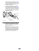
E.Raiseandlowerthedeckandcheckthe
dimensionsforcorrectalignment.Tighten
thejamnutto155N•m(114ft-lb)onthe
shock-armassembly.
Note:Becauseofdifferencesingrass
conditionsandthecounterbalancesetting
ofthetractionunit,cutthegrassandcheck
itsappearancebeforemowingtheentire
lawn.RefertothetractionunitOperator's
Manualfordecklevelingprocedures.
3