
Installation Instructions


FORM NO. 3316-574
The Toro Company1993
CRUISE CONTROL KIT
MODEL NO. 30485
INSTALLATION
INSTRUCTIONS
For Groundsmaster 455
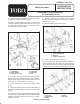
1. Remove screws securing steering column cover to
steering column frame. Remove cover.
2. Mount coil assembly to right side of center frame
member of steering column frame with (4) 1/4-20 x 1/2
lg. capscrews and nuts (Fig. 1). Position coil wire
harness toward front of machine.
Figure 1
1. Coil assembly
2. Frame member
3. Compression spring
4. Clutch plate
5. Clutch shaft
6. Collar
3. Insert hex end of clutch shaft into coil assembly,
aligning hole in end of shaft with hole in frame member.
Secure clutch shaft to frame member with a 3/8-16
screw (Fig. 1). Torque screw to 30-35 ft-lb.
4. Insert compression spring onto clutch shaft
(Fig. 1).
5. Slide clutch plate onto clutch shaft while aligning
spring with bushing flange on coil side of clutch plate
(Fig. 1).
6. Install and loosely secure collar to clutch shaft with
setscrew (Fig. 1). Push collar onto shaft until clearance
between clutch plate and coil is 3/32" (Fig. 1, inset).
Tighten set screw.
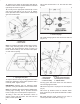
7. Remove capscrew, (2) washers and locknut
securing traction linkage rod ball joint to traction
linkage lever (Fig. 2).
8. Remove bushing from lever (Fig. 2).
Figure 2
1. Traction linkage rod
2. Ball joint
3. Traction linkage lever
9. Insert nylon sleeve onto cruise nut.
10. Secure cruise nut, sleeve and washer to left side of
traction linkage lever and ball joint with previously
removed capscrew and new spacer, while positioning
components in clutch plate slot as shown in figure 3.
Figure 3
1. Cruise nut
2. Nylon washer
3. Washer
4. Spacer
5. Ball joint