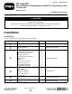
Form No. 3396-270 Rev A CE Light Kit 2014 and Before Groundsmaster® 4500/4700 or Reelmaster® 7000 Traction Unit Model No. 30491 Installation Instructions WARNING CALIFORNIA Proposition 65 Warning This product contains a chemical or chemicals known to the State of California to cause cancer, birth defects, or reproductive harm. Installation Loose Parts Use the chart below to verify that all parts have been shipped.
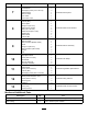
Procedure Description Switch-panel enclosure Control decal Self-tapping screw (1/4 x 1/2 inch) Hazard switch Beacon switch Horn switch Horn-button cover Carriage bolt (#10 x 5/8 inch) Locknut (#10) Sensor plate Flange nut (1/4 inch) Brake-sensor bracket Bolts (1/4 x 3/4 inch) Slotted screw (#6 x 1 inch) Washer (#6) Brake sensor Locknut (#6) Beacon Beacon socket Beacon bracket (ROPS model) U-bolt Flange nut (3/8 inch) Beacon bracket (cab model) Screws Nuts Left light bracket Right light bracket Screw (5/8 x
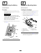
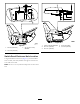
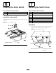
1 2 Disconnecting the Battery Drilling the Mounting Holes No Parts Required No Parts Required Procedure Installing the Headlights 1. Position the traction unit on a level surface, set the parking brake, lower the cutting units, turn the ignition off, and remove the key. 1. Remove the nuts from the 2 carriage bolts securing the headlights to the traction-unit frame (Figure 2). 2. Remove the 2 slotted screws securing the top of the platform shroud to the frame (Figure 2). CAUTION 3.
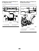
Figure 3 1. 6.35 cm (2-1/2 inches) 4. 1.0 cm (0.4 inch) diameter 2. 8.89 cm (3-1/2 inches) 5. 1.9 cm (3/4 inch) 3. 13.97 cm (5-1/2 inches) Drilling the Holes for the Horn Bracket Drilling a Hole in the Control Arm for the Flasher Module Using the dimensions shown in (Figure 4), locate and drill 2 holes 0.71 cm (0.28 inch) diameter through both walls of the roller-support tube. 1. Remove the 2 bolts that secure the plate to the right cover of the control arm (Figure 5).
Figure 7 Figure 6 1. 9.6 mm (0.38 inch) 1. 5.5 mm (.22 inch) diameter 4. 51 mm (2 inches) 2. 12.7 mm (1/2 inch) 3. 4.5 mm (0.17 inch) diameter 3. 12.7 mm (1/2 inch) 2. 12.7 mm (1/2 inch) Switch-Panel Enclosure Hole Location Using the dimensions shown in (Figure 7), locate and drill 3 holes 5.5 mm (.219 inch) diameter through the control-arm cover and control arm. Note: Do not to cut any internal components of the control arm. 5 5. 12.
Drilling Holes in the Rear Bumper for the Registration Plate Drilling holes in the Front Footrest for the Brake-Pedal Switch Using the dimensions shown in (Figure 8) to locate and drill 2 holes 9/32 inch diameter through the outside wall of the rear bumper. Using the dimensions shown in (Figure 9) to locate and drill 2 holes 9/32 inch diameter through the front footrest. Figure 8 1. 8.3 cm (3-1/3 inches) 3. 52.07 cm (20-1/2 inches) 2. 13.3 cm (5-1/4 inches) 4. 9/32 inch diameter Figure 9 1. 15.
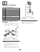
3 Installing the Headlights Parts needed for this procedure: 1 Right headlight-bracket assembly 1 Left headlight-bracket assembly 6 Screw (3/8 x 2-1/2 inches) 6 Flange nut (3/8 inch) 8 Flat washer (3/8 x 7/8 inches) 2 Rubber hanger 4 Spacer 4 Screw (5/16 x 1-5/8 inch) 4 Flange nut (5/16 inch) 1. Right headlight bracket 4. Headlight arm 1 Right-headlight assembly 2. Articulated joint shell 5. Locknut (10 mm) 1 Left-headlight assembly 3.
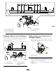
Installing the Headlight Bracket to a Cab Model 1. Loosely install a rubber hanger to the underside of each tab on the front of the cab with a bolt (5/16 x 1-5/8 inch), 2 washers (3/8 inch), a spacer, and a flange nut (5/16 inch) as shown in Figure 12. 2 1 1 3 4 2 G023182 Figure 13 1. Rubber hanger 3. Right headlight bracket 2. Bracket tab 4. Left headlight bracket 3 3.
• Front–Pop the lights out of the cab roof and disconnect 5 the wires from the lights. Install the lights into the cab. • Rear–Remove the screws securing the lenses to the lights. Remove the bulbs from the lights and install the lenses to the lights.
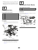
6 7 Installing the Relay Switch Installing the Switch Panel Parts needed for this procedure: Parts needed for this procedure: 1 Relay switch 1 Switch-panel enclosure 1 Bolt (#8 x 1/2 inch) 1 Control decal 3 Self-tapping screw (1/4 x 1/2 inch) 1 Hazard switch 1 Beacon switch 1 Horn switch 1 Horn-button cover Install the relay switch. Secure the relay switch with the bolt (#8 x 1/2 inch) as shown in Figure 17. Note: Do not overtighten bolt. Procedure 1.
2. Affix the light-panel decal onto the switch-panel enclosure as shown in Figure 19. 8 Note: Ensure that the surface is clean and dry before affixing the decal. Installing Brake-Sensor Bracket Parts needed for this procedure: Figure 19 1. Turn-signal switch 5. Light-panel decal 2. Horn-button cover 6. Switch-panel enclosure 3. Beacon switch 4. Hazard switch 7.
Figure 20 Figure 21 1. Forward footrest 4. Proximity sensor 2. Carriage bolt (#10 x 5/8 inch) 5. Brake-pedal lever 5. Brake-sensor bracket 1. Forward footrest 2. Slotted screw (#6 x 1 inch) 6. Locknut (#6) 3. Washer (#6) 7. Bolts (1/4 x 3/4 inch) 3. Brake-sensor plate 6. Locknut (#10) 4. Brake sensor 8. Flange nut (1/4 inch) 2.
lights when the brake pedal is pressed. Realign the brake sensor if necessary. 2. Position the beacon-light bracket 32 cm (12–5/8 inches) from the top of the ROPS and tighten the U-bolt nuts as shown inFigure 23. 9 Installing the Beacon Assembly Parts needed for this procedure: 1 Beacon 1 Beacon socket 1 Beacon bracket (ROPS model) 1 U-bolt 2 Flange nut (3/8 inch) 1 Beacon bracket (cab model) 2 Screws 2 Nuts G023191 Figure 23 3.
10 2 1 Installing the Rear Lamps Parts needed for this procedure: 1 Left light bracket 1 Right light bracket 4 Screw (5/8 x 3 inches) 4 Flat washer 2 Jam nut (5/8 inch) 2 Rear-lamp assembly 3 3 3 G023194 Figure 26 Procedure 1. Left light bracket 1. Remove the 2 bolts, 2 washers, and 2 nuts securing the reservoir-mounting bracket to the left frame rail (Figure 25). 3. Rear lamp 2. Right light bracket 3.
11 12 Installing the Registration-Plate Bracket Installing the Wiring Harness Parts needed for this procedure: Parts needed for this procedure: 1 Wire harness 1 Plate light 1 Switch-panel-enclosure cover 1 Plate bracket 3 Screw (#10 x 1/2 inch) 2 Screw (#10 x 5/8 inch) 3 Mounting pad 2 Locknut (#10) 11 Cable tie 2 Self-tapping screw (5/16 x 1/2 inch) Procedure Procedure Use the following instructions and illustrations to route and connect the wiring harness. 1.
1 1 2 2 3 4 G023200 Figure 32 G023198 Figure 30 1. Compartment clamp 1. Self-tapping screws (#8 x 1/2 inch) 3. Junction block 2. Ground-block terminal 4. Wiring-harness-fuse block 2. Seal 5. Connect the large-ring terminal, from the wiring harness, to the stud on the junction block (Figure 32). 2. From under the right side of the traction unit, route the fuse-block section of the wiring harness up to and into the opening in the fuse compartment (Figure 31). 6.
4 8. Route the harness to the switch-panel-enclosure and plug the connectors into the horn, beacon, turn signal, and hazard switches. 3 2 9. Install the switch-panel-enclosure cover to switch-panel enclosure with 3 screws (#10 x 1/2 inch) as shown in Figure 34. 1 1 5 g023241 Figure 36 1. Platform shroud 2. Headlight 4. Washer-head screws and nuts 5. Headlight-wire connectors 3. Carriage bolt and nut G023244 Figure 34 15.
1 2 G023204 Figure 38 1. Mounting pad 2. Cable tie Figure 40 19. Route the right rear wiring harness under the right side of the traction unit to the right rear light (Figure 39). 22. Plug the wiring harness connector into the light connector. 23. Route the wiring harness to the registration plate light and plug the wiring harness connector into the light connector, if applicable (Figure 40). Important: Secure the wiring harness with cable ties so that it does not contact any hot or moving parts. 24.
14 Connecting the Battery No Parts Required Procedure Connect the negative battery cable to the battery post (Figure 43). Figure 41 1. Fuse (10 A) 3. Fuse (10 A) 2. Fuse (10 A) 4. Fuse (15 A) 2. Install the fuse-box decal to the storage-box cover (Figure 42). Figure 43 1. Positive battery cable Figure 42 1. 6.25 mm (1/4 inch) 2. Fuse-box decal 19 2.
Operation Controls Hazard Switch Press the hazard switch (Figure 44) to the On position to activate the front and rear flashing hazard lights. 2 3 4 1 G023206 Figure 44 1. Hazard switch 2. Turn signal switch 3. Beacon switch 4. Horn button Turn-Signal Switch Press down on the left side of the turn-signal switch (Figure 44) to activate the left-turn signal. The center position is off. Press down on the right side of the turn-signal switch (Figure 44) to activate the right-turn signal.