
Installation Instructions
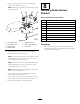


2.Afxthelight-paneldecalontotheswitch-panel
enclosureasshowninFigure19.
Note:Ensurethatthesurfaceiscleananddrybefore
afxingthedecal.
Figure19
1.Turn-signalswitch5.Light-paneldecal
2.Horn-buttoncover
6.Switch-panelenclosure
3.Beaconswitch7.Hornswitch
4.Hazardswitch
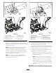
3.Installtheturn-signalswitchintotheleftholein
switch-panelenclosure(Figure19).
Note:Theturn-signalswitchisanOn-Off-Onswitch.
4.Installthebeaconswitchintothetopholeinthe
switch-panelenclosure(Figure19).
Note:ThebeaconswitchisanOn-None-Onswitch.
5.Installthehazardswitchintotherightholeinthe
switch-panelenclosure(Figure19).
Note:ThehazardswitchisanOn-None-Onswitch
andhasahazardsymbolonit.
6.Insertthehornbuttonupthroughtheholeinthe
switch-panelenclosure(Figure19).
7.Securethehornbuttontotheswitch-panelenclosure
bythreadingontherubber-hornbutton(Figure19).
8.Connecttheswitchestothewiringharness.
8
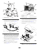
InstallingBrake-Sensor
Bracket
Partsneededforthisprocedure:
1
Carriagebolt(#10x5/8inch)
1
Locknut(#10)
1
Sensorplate
2
Flangenut(1/4inch)
1Brake-sensorbracket
2
Bolts(1/4x3/4inch)
2
Slottedscrew(#6x1inch)
4
Washer(#6)
1Brakesensor
2
Locknut(#6)
Procedure
1.Disassembletheproximity-sensorassemblyonthe
brake-pedallever(Figure20)andsetasidealltheparts
excepttheproximitysensor.
11