
Installation Instructions


8.Routetheharnesstotheswitch-panel-enclosureand
plugtheconnectorsintothehorn,beacon,turnsignal,
andhazardswitches.
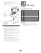
9.Installtheswitch-panel-enclosurecovertoswitch-panel
enclosurewith3screws(#10x1/2inch)asshownin
Figure34.
1
G023244
Figure34
1.Switch-panel-enclosurecover
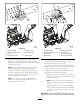
10.Routethefrontendofthewiringharnessunderthe
operatorplatformtothefrontofthetractionunit
(Figure35).
Figure35
11.Threadeachharnessconnectorthroughtheappropriate
headlightbracketandconnectittotheheadlight
(Figure35).
12.Plugthewiringharnesslead,withthe2connectors,
intothehorn(Figure35).
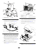
13.Positiontheplatformshroudontopoftheframe
(Figure36).
14.Plugthelight-kitwiringharnessconnectorsintothe
shroudheadlights(Figure36).
1
2
3
4
g023241
5
Figure36
1.Platformshroud
4.Washer-headscrewsand
nuts
2.Headlight5.Headlight-wireconnectors
3.Carriageboltandnut
15.Securetheshroudandtheheadlightstotheframe
withthe2carriageboltsandnutsyouremoved
previously(Figure36).
16.Routetherearsectionofthewiringharnesstotheright
uprightoftheROPSorcab(Figure37).
Figure37
Note:Connectthewiresforthebeaconandtherear
lightstothewiringharnessforthemainlightkit.
17.RoutethewiringharnessuptheROPSorcabpostand
plugitintothebeaconsocket(Figure38).
18.Afxthe3mountingpadstotheROPSorcabpost,
andsecurethewiringharnesstothepadswith3cable
ties(Figure38).
17