
Installation Instructions
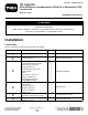
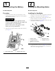
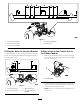
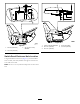
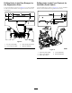
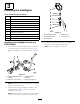

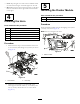
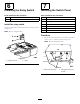

Figure3
1.6.35cm(2-1/2inches)4.1.0cm(0.4inch)diameter
2.8.89cm(3-1/2inches)5.1.9cm(3/4inch)
3.13.97cm(5-1/2inches)
DrillingtheHolesfortheHornBracket
Usingthedimensionsshownin(Figure4),locateanddrill
2holes0.71cm(0.28inch)diameterthroughbothwallsof
theroller-supporttube.
Figure4
1.1.9cm(0.75inch)3.25.4cm(10inch)
2.3.81cm(1-1/2inch)4.0.71cm(0.28inch)
diameter
DrillingaHoleintheControlArmfor
theFlasherModule
1.Removethe2boltsthatsecuretheplatetotheright
coverofthecontrolarm(Figure5).Removetheplate
fromthecontrolarm.
1
G023187
Figure5
1.Control-armplate
2.Usingthedimensionsshownin(Figure6),locateand
drilla4.5mm(0.17inch)diameterholethroughthe
control-armcoverandcontrolarm.
Note:Donottocutanyinternalcomponentsofthe
controlarm.
4