MODEL NO. 30502 FORM NO. 3317699 INSTALLATION INSTRUCTIONS TOR, ( 52” BLOWER KIT GROUNDS MASTER 200 X 52” SERIES A SAFETY INSTRUCTIONS BEFORE OPERATING 1. Read and understand the contents of this manual before starting and operating the machine. Become familiar with all controls and know how to stop quickly. A ire replacement manual is available by sending complete Mode! and Serial Numbers to: The Toto Company 8111 Tyndale Avenue South Minneapolis, Minnesota 55420 2.
A SAFETY INSTRUCTIONS 18. Using the machine demands the operator's complete attention. Ta prevent loss of control: A. Operate only in daylight or when there is good artificial light. Drive slowly. Avoid sudden starts and stops. Look behind machine before backing up. Watch for holes or other hidden hazards. " Do not drive close to a sand trap, ditch, creek, or hazard, . Reduce speed when making sharp turns and when turning on 2 hillside. H.
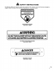
A SAFETY INSTRUCTIONS The following safely and instruction decals are mounted on the machine. If any decal becomes damaged or illegible, install a new decal. Part numbers are listed below or in your parts catalog. OR ENTIRE CATCHER IN PLACE DANGER | KEEP HANDS and FEET AWAY ON BLOWER HOUSING (Part No. 549220 | WARNING J ] DO NOT RUN BLOWER WITHOUT DISCHARGE CHUTE ATTACHED AND HOPPER IN LOWERED POSITION. oo ON FRONT OF BLOWER HOUSING {Part No.
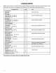
Note: Use this chart as a checklist to assure all parts necessary for assembly have been received. Without these LOOSE PARTS parts, total set-up cannot be completed. Some parts may have already been assembled at factory. Cap screw x 7/8" lg. Cap screw x 5/8" Ig. Lockout DESCRIPTION Qv USE Double Pulley Pulley Nut Install new Pulley Nut Cover Front Baffle Mount Front Baffle to Deck Rear Baffle Cap screw 5/16 — 18 x 7/8” lg.
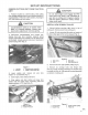
SET-UP INSTRUCTIONS REMOVE CUTTING UNIT FROM TRACTION UNIT 1. Position machine on a level surface, raise curling unit, engage parking brake, be sure traction pedal is in neutral position, PTO lever in OFF position, shut engine OFF and remove key from switch. A CAUTION Counterbalance spring Is In tension when deck is in lowered position. Always raise tech before adjusting or removing spring. 2.
SET-UP INSTRUCTIONS 5. Remove nut retaining pulley on spindle shaft. Remove pulley from saith. 8. Slide new double spindle pulley onto spindle shaft. Do not install pulley mut at this time. 7. Slide pulley end of spindle housing assembly through hole in curling unit, and loop belt around pulley and idler. Mount spindle assembly in place with support ring and six bandage bolts and flange nuts. 8. install new pulley nut onto spindle heft and tighten to 100 phi--b. Install nut cover.
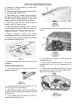
SET-UP INSTRUCTIONS 9. Drill holes in deck, ¥ required. 10. Mount center balls to deck with (4) 3/8 — 16x 1" fg. cap screws and lock washers (Fig. 9). 11. Using center baffle as a template, mark and drill (2) 9/32" dia. holes through center of curved edge of deck (Fig. 9). 12, Secure baffle to edge of deck with (2)1/4 — 20 x 3/4" ig. setscrews and lockouts (Fig. 9). 13, Align right ring baffle with end of center baffle and edge of deck (Fig. 9). Mark and drill (3) 8/32” dia.
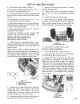
SET-UP INSTRUCTIONS 4. Disengage idler lever and mount idler assembly io deck with (3) 5/18 —18 x 3/4° lg. cap screw, 5/18 washers and lockout. Position washer between nut and idler assembly. 5. Engage tidier lever and check belt tension. Adjust necessary. REPOSITION COUNTERBALANCE SPRING 1. Remove fasteners securing counterbalance spring mounting bracket to front of traction unit frame (Fig. 13). L Figure 13 1.
SET-UP INSTRUCTIONS INSTALL CUTTING UNIT TO TRACTION UNIT 1. Engage parking brake, assure inaction pedal is in neutral and PTO lever is In OFF position. Start engine and raise earner. Stop engine. 2. Remove clevis pins and hairpin cotters from forward and rear height—of—cut brackets, 3. Position cutting unit under frame. Align gear case input shaft with PTO shaft and install the shaft, 4. Carefully lower carrier frame. Align PTO shaft hole with gear case input shaft hole and install tall pin.
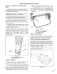
SET-UP INSTRUCTIONS 2. Draw lines around all sides of the chute and cut off with a saw. Mote: For convenience, some chutes have a light scribe mark where the chute must be cut off. 3. Set deck into desired height-of-cut settling. 4. Slide chute over blower opening and onto mounting studs (Fig. 21). 5. Lower hopper hood and align chute with hood snout. Secure chute in position with (4} 5/16 lockouts and chute brackets. Wide end of brackets to be positioned to rear (Fig. 21). Figure 21 1. Hate 2.
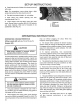
OPERATING INSTRUCTIONS 8. While operating, check frequently for excessive clippings left or turf or uncut grass. i those conditions occur, the blower or curling unit may be plugged. Stop unit, disengage PTO, set brake and shut off ignition. Check tor obstructions in the chute, blower or cutting unit. Clear any obstruction using & stick or similar ool Check blower belt tension. If slipping, readjust.
The Toto Promise A One Year Limited Warranty The Toto Company promises to repair your TOR product if defective in materials or workmanship. The following time periods from the date of purchase apply: Commercial Products The cost of parts, labor and transportation are included. If you feel your TOR Product is defective and wish fo rely on The Toto Promise, the following procedure is recommended: 1.