FORM NO. 3318-172 MODEL NO. 30505 60001 & UP INSTALLATION INSTRUCTIONS TOR, 15 CU. FT. HOPPER KIT Grounds master! 22ND, 22ND & 223RD A SAFETY INSTRUCTIONS IMPORTANT: On Model 30784, GM 220~D or Model 30224, GM 224 traction units with serial numbers prior to 16001, the steering cylinder rod end must be checked to assure it has a grease groove. If rod end does not have grease groove, a new rod end must be installed.
A SAFETY INSTRUCTIONS 15. The grass deflector or compete blower assembly must always be installed on cutting unit, 16. To maintain machine control, 75 Ib. of weight must be mounted on deft front whee! of traction unit before using the 15 cu. & Hopper kit. 17. Operator must ke skilled and trained in how to drive on hillsides. Failure to use caution on slopes or hills may cause loss of contra and vehicle to tip or roll possibly reselling in personal injury or death. 8. Traverse slopes carefully.
A SAFETY INSTRUCTIONS 34, Stay away from hopper and hopper linkage dung aeration. 35. Do not walk under hopper or service making unless hopper Is fully raised and empty, with hydraulic lines disconnected at quick couplets or fully lowered. 36. Do not remove any hydraulic ling unless hopper is Hull dowered or fully raised and empty. 3. If major repairs are ever needed or assistance is desired, contact an Authorized TOR Distributor. 38.
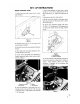
SET-UP INSTRUCTIONS MOUNT CONTROL VALVE 1. Place a drain pan under lift valve (Fig. 1} on right dice of making, Figure { 1. Afterlives 2. Discontent return line (Fig. 1), from bottom of it valve {fine goes to radiator). 3. Mount deft control valve tube assembly to filing on lift valve. 4. Mount right control valve ube assembly fo return ling disconnected from lift valve. 5, Loosely mount appropriate tube assemblies 1o fittings on right and left sides of valve, positioning them as shown in figure 1.
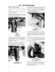
SET-UP INSTRUCTIONS MOUNT HOPPER FRAME 1. Disconnect air cleaner hose from air cleaner body Fig. 5). 2. Loosen bands securing air cleaner body to mounting brackets (Fig. 5). 3. Remove (4) screws securing air cleaner mounting brackets to left side of frame {Fig. 5). Remove air cleaner brackets. Discard fasteners Figure 5 1. Air Cleaner 2. Hose 3. Mounting Bracket 4.
SET-UP INSTRUCTIONS 11. Fran rear of machine, side front of hopper frame onto side mounting bracket pins and rear of frame over rear bracket pin. 12. Secure rear of frame to bracket pin with disconnect pin {Fig. 8). Figure 9 1. Disconnect Pin 13. Install short and loony welded mounting pins through arm assembly and main Sift arm assembly {Fig. 10). Secure with x 3/4” Ig. self tapping screws. Figure 10 1. Am Assembly 2. Hin Lift Arm Assembly 3. Short Pin {on fell side} 4.
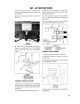
SET-UP INSTRUCTIONS MOUNT HOPPER ASSEMBLY 1. Remove tie straps securing tie rods to gopher mams. Install {2} 5/16 carriage bolts and flange nuts in hopper arm heels where fie straps previously Were. 2. Slide hopper assembly (hopper cover 10 rear) info side frame aligning mounting holes in hopper with holes in frame {Fig. 13) Figure 13 1. Hopper Assembly 2. Mounting Pins 3. Secure hopper to frame with (2} welded mounting pins and hair pin cotters (Fig. 13). 4.
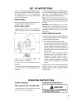
SET-UP INSTRUCTIONS 3. of material off bosom edge of top shield. Secure top shield to upper inside lip of hipper opening with 3 short fiat, screws and #10-24 flange nuts {Fig. 16). Uss {2) mounting holes on left side of opening Monty, INSTALL DECALS Install valve operation decal to right side of seat frame and caution decal to left side of seat mare. MOUNT WHEEL WEIGHT 1. Measure depth of wheel dm. This is achieved by measuring the distance from hole fo outside edge of fim, Figure 17 1. Whee! Weight 2.
OPERATING INSTRUCTIONS For best performance, regulate traction pedal to keep engine rom ti and somewhat constant. A good rule to follow is: decrease ground speed as the load on the citing blade increases; and increases ground speed as the load on the blade decreases.
MAINTENANCE ADJUSTING REAR COVER LATCH Adjust latch assembly {Fig. 18) up or down if cover does not seal properly of if cover dis not latch when operating. Figure 18 1. Latch Assembly A\ caution Never work on hopper unless it is in the lowered position. GENERAL PRACTICES 1. Keep unit clean, checking that engine is free of din and chaff. Make sure all fasteners are tight. Check deflectors. baffles and shields for wear and replace as sadness. 2.
The Toto Promise A One Year Limited Warranty The Toto Company promises 1o repair your TOR product if defective in materials or workmanship, The following time periods from the date of purchase apply: Commercial Products The cost of parts and labor are included, but the customer pays the transportation costs on walk rosary mowers with cutting unit widths of Jess than 25", tryout ee| your TOR Products defective and winsomeness states do not allow limitations on how long rely on The Toto Promise, the following