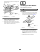
Form No. 3429-505 Rev A 62in Blower Kit Groundsmaster® 200/3280-D/3320 Series Side Discharge Mowers Model No. 30506—Serial No. 403000001 and Up Operator's Manual This product complies with all relevant European directives. For details, please see the Declaration of Incorporation (DOI) at the back of this publication. WARNING CALIFORNIA Proposition 65 Warning Use of this product may cause exposure to chemicals known to the State of California to cause cancer, birth defects, or other reproductive harm.
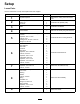
Setup Loose Parts Use the chart below to verify that all parts have been shipped. Procedure Description Qty. Use 1 No parts required – Remove the cutting unit from traction unit. 2 Double pulley Pulley nut Nut cover 1 1 1 Install the new spindle pulley. Blade 3 Install the new blades. Pivot brackets 2 Remove and modify the grass deflector.
Procedure Description 10 11 12 13 14 15 16 Use Qty. Bumper Capscrew, 5/16 x 3 inch Locknut, 5/16 inch Trim molding Deck cover Belt guard Pulley guard 1 4 4 1 1 1 1 Counterbalance spring 1 Install the new counterbalance spring. No parts required – Install the cutting unit to the traction unit. Decal, danger 1 Install the new decal. Chute assembly 1 Mount the blower housing chute. Install bumper Install the new deck cover. Install the new safety guards.
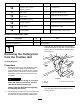
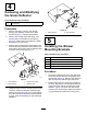
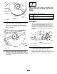
2 Installing the New Spindle Pulley g012557 Figure 2 2. Right castor arm 1. Lift arm bracket Parts needed for this procedure: 4. Start the engine and raise the traction unit lift arms. 5. Shut off the engine and slide the cutting unit away from the traction unit, separating the male and female sections of PTO shaft (Figure 3). 1 Double pulley 1 Pulley nut 1 Nut cover Procedure 1. 2. Unhook the latches securing the right cover to the top of the cutting unit.
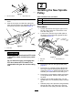
spindle assembly in place with 6 carriage bolts and flange nuts. 3 Installing the New Blades Parts needed for this procedure: 3 Blade Procedure 1. g012535 Figure 5 1. Carriage bolts Grasp the end of blade using a thickly padded glove. Remove the blade bolt, anti-scalp cup, and blade from the spindle shaft (Figure 6). 3. Pulley nut 2. Double spindle pulley 8. Install the original washer and new pulley nut onto the spindle shaft and tighten it to 100 ft-lb (135.5 N⋅m). Install the nut cover. 9.
4 Removing and Modifying the Grass Deflector Parts needed for this procedure: 2 Pivot brackets Procedure g012537 Figure 8 1. Remove the bolts, locknuts, and springs securing the deflector mounts to the pivot brackets (Figure 7). Remove the deflector. 2. Remove the carriage bolts and flange nuts securing the pivot brackets to the housing (Figure 7). Remove the pivot brackets. Retain the fasteners for future use. 3. 1. Grass deflector 2.
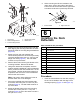
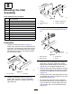
9. When mounting the lift arm brackets to the castor arms, mount other side of the blower brace to the lift arm bracket and the right castor arm with the bolt and nut previously removed. g012557 Figure 10 1. Lift arm bracket 6 g012538 Figure 9 1. Spring latch 4. Reinforcement plate 2. Rear mounting bracket 5. Blower brace 2. Right castor arm Installing the Deck Deflectors 3. Front mounting bracket Parts needed for this procedure: 3.
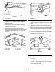
g012539 g012541 Figure 11 Figure 13 1. Front deflector 1. Rear deflector 2. Using the deflector as a template, mark and drill three 11/32 inch diameter holes through front and top of deck. 5. Using the deflector as a template, mark and drill three 11/32 inch diameter holes through the deck. 3. Secure the 2 front mounting tabs of deflector to the deck with bolts (5/16-18 x 5/8 inch) and locknuts (5/16-18 inch). 6.
7 Mounting the New Deflector Stop Parts needed for this procedure: 1 Deflector stop 2 Capscrew, 1/4 x 3/4 inch 2 Locknut, 1/4 inch g012543 Figure 15 1. Left shelf Procedure 11. Align the right shelf with the right end of the rear shelf and the edge of the deck (Figure 12 and Figure 16). Using the left shelf as a template, locate, mark, and drill three 9/32 inch diameter holes in the deck. 1. Using the new deflector stop as a template, set it on the original flat deflector stop (Figure 17).
8 Mounting the Idler Assembly Parts needed for this procedure: g012547 Figure 19 1 Idler arm assembly 1 Pivot screw 1. 5 inches 4. 13/32 inch diameter (2) 1 Bushing 2. 1-1/16 inches (2) 5. 13/16 inch diameter 2 Washer 3. 1 inch 1 Locknut, 3/8 inch 1 Spring 1 Threaded rod 2 Flange nut, 5/16 inch 1 Spring bracket 2 Capscrew, 1/4 x 1 inch 2 Locknut, 1/4 inch 3. Thread a flange nut (5/16-18 inch) approximately 2 inches (5 cm) onto the threaded rod (Figure 20). Procedure 1.
Important: Do not tighten the flange nuts on the threaded rod at this time. Adjust the spring tension after the blower assembly and belt have been installed. 10 Install the Bumper 9 Parts needed for this procedure: Mounting the Blower Parts needed for this procedure: 1 Belt 1 Bumper 4 Capscrew, 5/16 x 3 inch 4 Locknut, 5/16 inch Procedure 1. Procedure 1. Route the belt around the small deck spindle pulley. 2.
mounting bolt with the hole in the right castor arm. The cover is to rest on the trim molding. Adjust the molding as required. 3. Secure the cover to the right castor arm with the bolt. 12 1. Bumper Installing the New Safety Guards 3. Parts needed for this procedure: g012551 Figure 23 Using both mounting plates of the bumper as templates, locate, mark, and drill 3 additional 11/32 inch diameter holes through both walls of the front and rear castor arm brackets.
g012553 Figure 27 g029099 Figure 26 1. Pulley guard 3. Bolt 1. Hair pin cotter 4. Spring 2. Clevis pin 5. Bottom bracket 3. Top bracket 2. Nut 4. Note: Use existing hardware on the machine Install the spring assembly into the retaining bracket with a clevis pin and hairpin cotter. by removing it and using it to install the guard. 14 13 Installing the Cutting Unit to the Traction Unit Installing the New Counterbalance Spring (200 Series traction units only) No Parts Required Procedure 1.
15 Installing the New Decal 2. Draw lines around all sides of the chute and cut off with a saw. 3. Set the deck to the desired height-of-cut setting. 4. Slide the chute over the blower opening and onto the mounting studs (Figure 29). Parts needed for this procedure: 1 Decal, danger Procedure Install the Danger Decal (Part Number 66-1340 or 93-7824 for CE) on the front edge of the deck, inside the right castor arm. 16 g012555 Figure 29 1. Chute Mounting the Blower Housing Chute 5.
Operation 4. While operating, check frequently for excessive clippings left on the turf or uncut grass. If those conditions occur, the blower or cutting unit may be plugged. Shut off the unit, disengage the PTO, set the brake, and shut off the engine. Check for obstructions in the chute, blower or cutting unit. Clear any obstruction using a stick or similar tool. Check the blower belt tension. If it is slipping, readjust the tension. 5. Cut grass often, especially when it grows rapidly.
Maintenance Using the Grass Deflector At some time you may wish to operate the cutting deck without the blower. Since a new pivot should have already been installed on the grass deflector, you can quickly mount the deflector to the blower mounting brackets. 1. Remove the bumper from the deck. 2. Slide the slots at bottom of the deflector pivot bracket onto the bolts at side of the deck brackets (Figure 30). • Check the blower gearbox impeller for tightness every 50 hours.
Declaration of Incorporation Model No. 30506 Serial No. Product Description Invoice Description General Description Directive 403000001 and Up 62in Blower Kit, Groundsmaster 200/3280-D/3320 Series Side Discharge Mowers GM200 62" BLOWER KIT 62in Blower Kit 2006/42/EC, 2000/14/EC Relevant technical documentation has been compiled as required per Part B of Annex VII of 2006/42/EC.
EEA/UK Privacy Notice Toro’s Use of Your Personal Information The Toro Company (“Toro”) respects your privacy. When you purchase our products, we may collect certain personal information about you, either directly from you or through your local Toro company or dealer.
California Proposition 65 Warning Information What is this warning? You may see a product for sale that has a warning label like the following: WARNING: Cancer and Reproductive Harm—www.p65Warnings.ca.gov. What is Prop 65? Prop 65 applies to any company operating in California, selling products in California, or manufacturing products that may be sold in or brought into California.
The Toro Warranty Two-Year or 1,500 Hours Limited Warranty Conditions and Products Covered Parts The Toro Company and its affiliate, Toro Warranty Company, pursuant to an agreement between them, jointly warrant your Toro Commercial product (“Product”) to be free from defects in materials or workmanship for 2 years or 1,500 operational hours*, whichever occurs first. This warranty is applicable to all products with the exception of Aerators (refer to separate warranty statements for these products).