
Installation Instructions

3
2
1
G015966
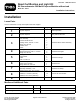
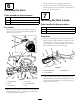
Figure4
1.1inch(25mm)3.1–5/8inches(41mm)
2.2inchdiameter(51mm)
3.Removeallburrsandroughedgesfromthedrilled
hole.Paintthenewlyexposedmetaltoprevent
rusting.
3
InstallingtheSwitchColumn
Assembly
Partsneededforthisprocedure:
1
Columnbracketassembly
1Hornassembly
1
Columnbracketmount
2
Carriagescrew,3/8inchx1inch
2
Flangenut,3/8inch
1
Columncover
2
Screw
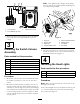
Procedure
1.Mountthehornswitchtothecolumnbracketwith
therubberhornbutton().Donotusethesilver
button
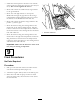
2.Mountthecolumnbracketassemblytotherearof
steeringcolumnwiththecolumnbracketmount,(2)
3/8inchx1inchcarriagescrewsand3/8inchange
nuts.Positionthecolumnbracketashighaspossible
onthesteeringcolumnasshowninFigure5.Make
surethecolumnbracketdoesnotinterferewiththe
steeringwheel.
Note:Overtighteningthecarriagescrews/ange
nutsmaydistortthecolumnbracketprohibitingthe
coverfrombeinginstalled.
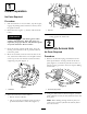
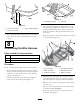
Figure5
1.Screw(2)5.Columnbracketassembly
2.Columncover6.Carriagescrew
3.Flangenut7.Hornbutton
4.Columnbracketmount
8.Hornswitch
3.Afterthewireharnessisconnectedtotheswitches,
mountthecolumncovertothecolumnbracket(2)
speednutswithscrews(Figure5).
4
InstallingtheHeadLights
Partsneededforthisprocedure:
1
Headlightassemblyw/wireharness
2
Flangeheadscrew,3/8x1–1/2inch
2
Flangenut,3/8inch
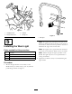
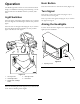
Procedure
Note:Makesurethewireharnessexitstherearofthe
headlightmounttube.
Securetheheadlightmounttotheplatformwith(2)3/8
x1–1/2inchangeheadscrewsand3/8inchange
nutsasshownin
Figure6.
3