
Installation Instructions
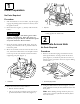
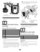
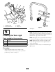
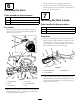
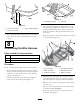
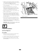
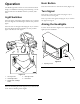

Figure10
1.2.25inches(57mm)3..350inchdiameter(9mm)
2.2.55inches(65mm)
3.Removeallburrsandroughedgesfromthedrilled
holes.Paintthenewlyexposedmetaltoprevent
rusting.
8
ConnectingtheWireHarness
Partsneededforthisprocedure:
1
Grommet
13
Cabletie,7–1/4inch(184mm)
2
Cabletie,14–1/2inch(368mm)
Procedure
Route,connectandsecurethewireharnessasfollows:
•Routetheharnesswiththe(5)connectorsupthe
steeringcolumnandplugthemintotheappropriate
connectors.Cabletietheharnesstothesteering
columnwithcableties.
•Inserttheremainderoftheharnessthroughthe
knockoutholeintheoorplate(Figure11).
Figure11
1.Knockoutpluglocation
2.Grommet
•Cutaslitinthesuppliedgrommetandcutoutthe
bottomopening(Figure11).Withtheconeend
ofthegrommetfacingdown,wrapitaroundthe
harnessandinsertitintotheknockoutholeinthe
oorplate.
•Routetheharnesstohornandconnectthetwowires
totheterminals(
Figure12).
3
4
6
2
G015965
7
5
1
Figure12
1.Hornconnection4.Rearlampconnections
2.Switchconnection
5.Worklightconnector
3.Accessoryconnection6.Batteryconnection
•Followingtheexistingharness,routetheharness
alongtheundersideoftheseatsupportbracketto
thecontrolpanelontherightsideofthemachine.
•Removethe(5)screwssecuringthecontrolpanelto
thetankcover.
•Raisethecontrolpanelandlocatethewireharness
connectorlabeledAccessory.
•Routetheharnessconnectoruptotheaccessory
connectorandplugitin.
6