
Installation Instructions


3
2
1
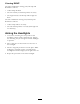
G015966
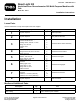
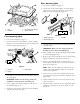
Figure4
1.1inch(51mm)3.1–5/8inches(41mm)
2.2inchdiameter(51mm)
3
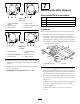
InstallingtheSwitchColumn
Assembly
Partsneededforthisprocedure:
1
Columnbracketassembly
1
Columnbracketmount
2
Carriagescrew,3/8inchx1inch
2
Flangenut,3/8inch
1
Columncover
2
Screw
Procedure
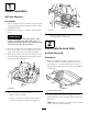
1.Mountthecolumnbracketassemblytothesteering
columnwiththecolumnbracketmount,(2)3/8inch
x1inchcarriagescrewsand3/8inchangenuts.
Positionthecolumnbracketashighaspossibleon
thesteeringcolumnasshownin
Figure5.Make
surethecolumnbracketdoesnotinterferewiththe
steeringwheel.
Note:Overtighteningthecarriagescrews/ange
nutsmaydistortthecolumnbracketprohibitingthe
coverfrombeinginstalled.
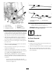
Figure5
1.Screw(2)5.Columnbracket
2.Columncover
6.Flangenut
3.Columnbracketmount7.Carriagescrew
4.Speednut(2)
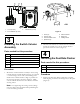
2.Afterthewireharnessisconnectedtotheswitches,
mountthecolumncovertothecolumnbracket
speednutswithtwoscrews(
Figure5).
4
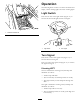
InstallingtheDualRateFlasher
Partsneededforthisprocedure:
1
Dualrateasher
2
Flangeheadscrew,#10x3/4inch
2
Flangenut,#10
Procedure
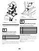
1.Positionthedualrateasherundertheseatplate
whilealigningitwiththemountingholesintheplate
(Figure6).
3