Form No. 3430-135 Rev A 62in Side Discharge Mower Groundsmaster® 200,1000, 3320 and 3280-D Series Traction Unit Model No. 30551—Serial No. 400000000 and Up Register at www.Toro.com.
This product complies with all relevant European directives. For details, please see the Declaration of Incorporation (DOI) at the back of this publication. WARNING CALIFORNIA Proposition 65 Warning Use of this product may cause exposure to chemicals known to the State of California to cause cancer, birth defects, or other reproductive harm. g243406 Figure 1 1. Serial number location Introduction Model No.
Contents Safety ....................................................................... 4 General Safety ................................................... 4 Cutting Unit Safety.............................................. 4 Safety and Instructional Decals .......................... 5 Setup ........................................................................ 8 1 Installing the Castor Wheel Assemblies............ 8 2 Installing the Lift Arms......................................
Safety This machine has been designed in accordance with ANSI B71.4-2017 and EN ISO 5395. General Safety This product is capable of amputating hands and feet and of throwing objects. Always follow all safety instructions to avoid serious personal injury. • Read and understand the contents of this Operator’s Manual before starting the engine. • Use your full attention while operating the machine. Do not engage in any activity that causes distractions; otherwise, injury or property damage may occur.
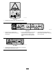
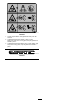
Safety and Instructional Decals Safety decals and instructions are easily visible to the operator and are located near any area of potential danger. Replace any decal that is damaged or missing. decal92-3035 92-3035 1. Height of cut decal105-9553 105-9553 1. Warning—read the Operator's Manual. 2.
decal107-2915 107-2915 1. Entanglement hazard, shaft—keep bystanders away. decal107-2916 107-2916 1. Remove the key and read the Operator's Manual before performing maintenance. 2. Thrown object hazard—do not operate the mower with the deflector up or removed; lower the deflector before using the machine; keep bystanders away. decal117-4979 117–4979 1. Entanglement hazard, belt—stay away from moving parts, keep all guards and shields in place. 6 3.
decal120-6604 120-6604 1. Thrown object hazard—keep bystanders away from the machine. 2. Cutting/dismemberment hazard of hand, mower blade—stay away from moving parts, keep all guards and shields in place. 3. Cutting/dismemberment hazard of foot, mower blade—stay away from moving parts, keep all guards and shields in place.
Setup Loose Parts Use the chart below to verify that all parts have been shipped. Procedure Description 1 2 3 4 5 6 Use Qty. Front castor wheel assembly Rear castor wheel assembly Right lift arm Left lift arm Pivot pin Cotter pin (5/32 x 1-3/4 inches) 2 2 1 1 2 2 No parts required – Connect the lift arms to the cutting unit. No parts required – Connect the PTO shaft and guard to the cutting unit gearbox. No parts required – Install the rear weight. No parts required – Grease the machine.
2. Slide the spacers onto the castor spindle to get the desired height of cut; refer to the chart in Adjusting the Height of Cut (page 12). 3. Slide a thrust washer onto the spindle, push the round castor spindle through the front castor arm, and the hex castor spindle through the rear castor arm. 4. Install another thrust washer and the remaining spacers onto the spindle and install the tensioning cap to secure the assembly.
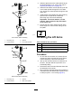
g010783 Figure 5 1. Pivot pin 3. Lift arm pivot bracket 2. Lift arm 4. Brake return spring g010784 Figure 6 5. Mount the rear of the lift arm to the lift cylinder with a pivot pin and 2 cotter pins (supplied with the traction unit). 1. Lift arm 2. Ball joint 6. Hook the brake return spring into the hole in the lift arm (Figure 5). 3. 7. Repeat this procedure for the opposite side of the machine. 3. Jam nut 4. 57 mm (2–1/4 inch) Move the lift lever to the FLOAT position.
Note: When tightening the jam nut, hold the ball 5 joint straight to permit proper oscillation during raising and lowering of the cutting unit. Installing the Rear Weight 4 No Parts Required Connecting the PTO Shaft and Guard to the Cutting Unit Gearbox Procedure Two-Wheel Drive Groundsmaster 1000 and 200 Series traction units comply with EN ISO 5395 and ANSI B71.4-2017 when equipped with rear weight.
Product Overview Operation Specifications Note: Determine the left and right sides of the machine from the normal operating position. Note: Specifications and design are subject to change without notice. Adjusting the Height of Cut Width of Cut 1.56 m (61-5/8 inches) Height of Cut Adjustable from 25 to 102 mm (1 to 4 inches) in 13 mm (1/2 inch) increments Blade Tip Speed 15,480 ft/minute @ 3250 engine rpm Cutting Blades 3 heat-treated steel blades, each 4.
g010786 Figure 9 1. Front castor wheel 3. Spacers 2. Tensioning cap 4. Thrust washers 2. Remove the washer from the spindle shaft. 3. Slide the spacers onto the spindle shaft to get the desired height of cut, then slide the washer onto the shaft. 4. Push the castor spindle through the front castor arm. 5. Install the other thrust washer and remaining spacers onto the spindle. 6. Install the tensioning cap to secure the assembly. g010787 Figure 10 1. Rear castor wheel 3. Spacers 2.
Adjusting the Rollers and Gage Wheel 2. Note: If you want to use the cutting unit in the 25 mm Adjusting the Rear (Internal) Rollers (1 inch) or 38 mm (1-1/2 inches) height-of-cut setting, position the cutting unit rollers in the top bracket holes. 1. Adjusting the Front Roller 1. Align the roller and spacer with the top holes in the brackets and secure them with the capscrew and nut. Remove the capscrew and nut securing the roller shaft to the cutting unit bracket (Figure 11).
Using the Grass Deflector position and adjust your ground speed for conditions. Decrease the ground speed as the load on the cutting blades increases. Increase the ground speed as the load on the blades decreases. DANGER Without a grass deflector, discharge cover, or complete grass catcher assembly mounted in place, you and others are exposed to blade contact and thrown debris. Contact with rotating mower blade(s) and thrown debris will cause injury or death.
Blade Maintenance Maintain a sharp blade throughout the cutting season because a sharp blade cuts cleanly without tearing or shredding the grass blades. Tearing and shredding turns grass brown at the edges, which slows growth and increases the chance of disease. Check the blades daily for sharpness, and for any wear or damage. Sharpen the blades as necessary. If a blade is damaged or worn, replace it immediately with a genuine Toro replacement blade.
Maintenance Recommended Maintenance Schedule(s) Maintenance Service Interval Maintenance Procedure After the first 2 hours • Tighten the castor wheel nuts. After the first 10 hours • Tighten the castor wheel nuts. Before each use or daily • Lubricate the castor arm bushings. • Lubricate the castor wheel bearings. After each use • Clean the cutting unit. Every 50 hours • Lubricate the grease fittings. • Check the gearbox lubricant. • Tighten the castor wheel nuts.
Important: The fasteners on the covers of this machine are designed to remain on the cover after removal. Loosen all the fasteners on each cover a few turns so that the cover is loose but still attached, then go back and loosen them until the cover comes free. This prevents you from accidentally stripping the bolts free of the retainers. Lubrication Service Interval: Every 50 hours The machine has grease fittings that you must lubricate regularly with No. 2 lithium grease.
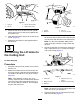
Separating the Cutting Unit from the Traction Unit 1. Position the machine on a level surface. 2. Lower the cutting unit to the floor, move the lift lever to the FLOAT position, engage the parking brake, put the traction pedal in neutral, set the PTO lever in the OFF position, shut the engine off, and remove the ignition key. 3. Remove the capscrews and locknuts securing the ball joint mounts to the castor arms on the cutting unit (Figure 19). g010552 Figure 20 1.
7. Use a hammer and flat plate to drive the bushings into the mounting tube. 3. Pull the spanner bushing out of the wheel hub (Figure 22). 8. Inspect the castor spindle for wear, and replace it if it is damaged. 4. Remove the bushing from the wheel hub and allow the bearing to fall out. 9. Push the castor shaft through the bushings and mounting tube. 5. Remove the bushing from the opposite side of the wheel hub. 10. Slide the thrust washer and spacer(s) onto the spindle. 6. 11.
2. Important: The curved part of the blade Rotate the blade until the ends face forward and backward and measure from the inside of the cutting unit to the cutting edge at the front of the blade (Figure 23). must point toward the inside of the cutting unit to ensure proper cutting. Note: After striking a foreign object, torque all spindle-pulley nuts to 115 to 149 N∙m (85 to 110 ft-lb). Note: Remember this dimension. Inspecting and Sharpening the Cutting Unit Blade(s) g010549 Figure 23 3.
Note: Remove the blades and sharpen them on a grinder. After sharpening the cutting edges, install the blade with the anti-scalp cup and blade bolt; refer to Removing and Installing the Cutting-Unit Blade(s) (page 21). Checking and Correcting Mismatch of Blades If a cutting blade cuts lower than the others, correct them as follows: 1.
g010557 Figure 28 2. Lower the cutting unit, engage the parking brake, put the traction pedal in neutral, the PTO lever in the OFF position, shut the engine off, and remove the ignition key. 3. Remove the cover from the center cutting unit. 4. Loosen the 2 nuts that secure the idler plate in place. 5. Use a socket and torque wrench to tighten the idler adjusting nut to 47 to 54 N-m (35 to 40 ft-lb) (Figure 29). 1. Measure from the blade tip to a level surface. 7.
PTO lever in the OFF position, shut the engine off, and remove the ignition key. 3. Remove the covers from the top of the cutting unit. 4. Loosen the 2 nuts that secure the idler plate in place, and remove the old belt from the pulleys. 5. To install a new belt, you must remove the gearbox by removing the 4 carriage bolts and locknuts holding the gearbox base. 6. Install the new belt around the gearbox pulley, spindle pulleys, stationary idler pulley, and adjustable idler pulley (Figure 30).
Storage 1. Disengage the PTO, release the traction pedal to the neutral position, lower the cutting unit, move the throttle lever to the SLOW position, and engage the parking brake. 2. Shut off the engine, remove the key, and wait for all movement to stop before you leave the operator's position. Allow the machine to cool before adjusting, servicing, cleaning, or storing it. 3.
Troubleshooting Problem The cutting unit does not cut or cuts poorly. Possible Cause Corrective Action 1. The blades are dull. 1. Sharpen the blades. 2. One or more blades are bent or damaged. 3. The spindle bolts are loose. 2. Replace the blades. 4. The cutting unit belts are loose or broken. 5. The gearbox pulley is loose. 6. A gearbox shaft is broken. 7. The PTO belt is broken. 8. The PTO pulley is loose or broken. 9. The PTO shaft is broken. 10.
Notes:
Notes:
Notes:
Declaration of Incorporation The Toro Company, 8111 Lyndale Ave. South, Bloomington, MN, USA declares that the following unit(s) conform(s) to the directives listed, when installed in accordance with the accompanying instructions onto certain Toro models as indicated on the relevant Declarations of Conformity. Model No. 30551 Serial No.
California Proposition 65 Warning Information What is this warning? You may see a product for sale that has a warning label like the following: WARNING: Cancer and Reproductive Harm—www.p65Warnings.ca.gov. What is Prop 65? Prop 65 applies to any company operating in California, selling products in California, or manufacturing products that may be sold in or brought into California.
The Toro Warranty Two-Year or 1,500 Hours Limited Warranty Conditions and Products Covered Parts The Toro Company and its affiliate, Toro Warranty Company, pursuant to an agreement between them, jointly warrant your Toro Commercial product (“Product”) to be free from defects in materials or workmanship for 2 years or 1,500 operational hours*, whichever occurs first. This warranty is applicable to all products with the exception of Aerators (refer to separate warranty statements for these products).