Form No. 3326-905 62 Side Discharge Mower Groundsmaster 200 Series Model No. 30551—Serial No.
Contents Introduction Page Introduction . . . . . . . . . . . . . . . . . . . . . . . . . . . . . . . . 2 Safety . . . . . . . . . . . . . . . . . . . . . . . . . . . . . . . . . . . . . 3 Safe Operating Practices . . . . . . . . . . . . . . . . . . . . 3 Toro Mower Safety . . . . . . . . . . . . . . . . . . . . . . . . 4 Safety and Instruction Decals . . . . . . . . . . . . . . . . 5 Specifications . . . . . . . . . . . . . . . . . . . . . . . . . . . . . . . 7 General Specifications . . . . . . . . . .
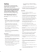
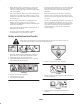
Safety – Never remove fuel cap or add fuel with engine running. Allow engine to cool before refueling. Do not smoke. This machine meets or exceeds the B71.4 1999 specifications of the American National Standards Institute, in effect at time of production. – Never refuel or drain the machine indoors. • Check that operator’s presence controls, safety switches and shields are attached and functioning properly. Do not operate unless they are functioning properly.
• The operator shall turn on flashing warning lights, if provided, whenever traveling on a public road, except where such use is prohibited by law. Operation • Know how to stop the machine quickly. • Always wear substantial shoes. Do not operate the machine while wearing sandals, tennis shoes, or sneakers. Maintenance and Storage • Disengage drives, lower the cutting units, move traction pedal to Neutral, set parking brake, stop engine and remove key and disconnect spark plug wire.
• Before disconnecting or performing any work on the hydraulic system, all pressure in the system must be relieved by stopping the engine and lowering the cutting units to the ground. • Perform only those maintenance procedures described in this manual. If major repairs are ever needed or if assistance is desired, contact an Authorized Toro Distributor.
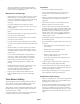
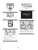
92-3035 1. Height-of-cut 54-9220 93-6696 1. Warning—the spring is under tension. Read the operator’s manual. 99-5172 93-7283 1. Entanglement hazard—keep bystanders away. 105-9553 1. Warning—read the Operator’s Manual. 2. Tipping hazard—lower the cutting unit when driving down slopes. Add a 25 kg (55 lb.) rear weight to GM 228D units and a 48 kg (105 lb.) rear weight to GM 225 units. 93-7824 1. Thrown object hazard—keep bystanders away. 2. Thrown object hazard from mower—keep the deflector in place. 3.
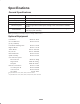
Specifications General Specifications Width of Cut 61-5/8 in. (1.56 m) Height of Cut Adjustable from 1 to 4 in. (25 to 102 mm) in 1/2 inch increments Blade Tip Speed Cutting Blades Unit Drive System Castor Wheels 15,480 ft./min. @ 3250 engine RPM 3 heat-treated steel blades, each 3/16 in. (4.8 mm) thick and 24-3/4 in. (55 cm) long PTO driven gear box transmits power through a “AA” section belts to all blade spindles. 8 in.
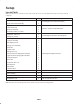
Setup Loose Parts Note: Use this chart as a checklist to ensure that all parts have been received. Without these parts, total setup cannot be completed. Description Qty. Use Front castor wheel assembly 2 Rear castor wheel assembly 2 Right-hand lift arm 1 Left-hand lift arm 1 Pivot pin assembly 2 Cotter pin, 5/32 in. x 1-3/4 in. 2 Capscrew, 7/16 x 3 in. 4 Flange nut, 7/16 in.
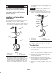
Install another thrust washer and the remaining spacers onto the spindle and install the tensioning cap to secure the assembly. Danger If the engine is started and the PTO shaft is allowed to rotate, serious injury could result. Important The thrust washers, not the spacers, must contact the top and bottom of the castor arm. Do not start the engine and engage the PTO lever when the PTO shaft is not connected to the gear box on the cutting unit. 3.
3. Move the lift lever to the Float position. Push the lift arms down until the holes in the ball joint mounts line up with the holes in the castor arms. 2 4. Secure the ball joint mounts to each castor arm with 2 capscrews (7/16 x 3 in.) and flange nuts (7/16 in.) (Fig. 5). Note: The ball joint mount should be above the castor arm when it is assembled. 1 5. Tighten the large jam nut securing the ball joint to the lift arm (Fig. 5).
Mounting the PTO Shaft Guard and Connecting the PTO Shaft to the Cutting Unit Gear Box 1. Remove the 2 capscrews and lock washers securing the PTO guard mounting brackets to the gearbox (Fig. 6). Retain the fasteners for future installation. 2. Slide the PTO shaft guard onto the PTO shaft, positioning the guard as shown in Figure 6. 3 2 1 4 3 Figure 7 1. 52″ side discharge deck 2. 52″ deck w/bagger 2 3. 62″ and 72″ decks 4. 52″ rear discharge deck 3.
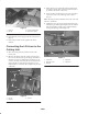
6. Mount the bottom of the knee link to the deck bracket with a shoulder bolt and locknut. Use the heavy rate extension on the left-hand side (large diameter spring wire) and the light rate extension spring on the right, discharge side (small diameter spring wire). 1 7. Align the slotted holes in the spring cover (slot toward the bottom) with the mounting bracket holes. Insert the lock pin assemblies into the bracket holes and secure each to the bracket with the self-tapping screws (Fig. 9).
Installing Rear Weight 2 Two Wheel Drive Groundsmaster 1000 and 200 Series traction units comply with the ANSI B71.4-1999 Standard when equipped with rear weight. Refer to the chart in the traction unit Operator’s Manual to determine the combinations of weight required. Order the parts from your local Authorized Toro Distributor. 4 Four Wheel Drive Groundsmaster 200 Series traction units do not need additional rear weight to comply with the ANSI B71.4-1999 Standard.
Adjusting the Front Gage Wheel 2. Remove or add ”C” shaped spacers at the narrow portion of the spindle shaft, below the castor arm, to get the desired height-of-cut. Make sure that the thrust washers, not the spacers, contact the top and bottom of the castor arm. 1. Remove the capscrew and nut securing the gage wheel to the cutting unit brackets (Fig. 15). 2. Align the roller and spacer with the top holes in the brackets and secure them with the capscrew and nut. 3.
Checking the Lubricant in the Gear Box Operation 1. Position the machine and cutting unit on a level surface. Note: Determine the left and right sides of the machine from the normal operating position. 2. Remove the fill/check plug from the side of the gear box (Fig. 17) and make sure that the lubricant is up to the bottom of the hole. If the lubricant level is low, add enough lubricant to bring it up to the bottom of the hole.
Adjusting the Tension Spring For best performance, the cutting unit bounce on uneven turf is minimal and it does not ride heavily over flat terrain. If scalping occurs or the cut is uneven from side to side, there may too much weight on the deck and weight may have to be transferred to the traction unit: i.e. increased spring tension. By contrast, if too much weight is transferred to the traction unit, the deck will bounce excessively and the cut will be uneven.
3 2 1 1 Figure 23 1. Lock pin 2. Bracket 3. Spring tension assembly Figure 22 4. Remove the capscrews and locknuts securing the ball joint mounts to the castor arms on the cutting unit (Fig. 24). 1. Fill/check plug Separating the Cutting Unit from the Traction Unit 2 1 1. Position the machine on a level surface, raise the cutting unit, engage the parking brake, put the traction pedal in neutral, the PTO lever in the Off position, shut the engine off, and remove the ignition key.
4. Insert a pin punch into the top or bottom of the mounting tube and drive the bushing out of the tube. Also drive the other bushing out of the tube (Fig. 26). Clean the inside of the tubes to remove dirt. 1 2 Figure 25 1. PTO shaft 1 Figure 26 Mounting the Cutting Unit to the Traction Unit 1. Front castor arm tube 1. Position the machine on a level surface and shut the engine off. 2. Bushings 5. Apply grease to the inside and outside of the new bushings.
6. Carefully slide the spanner through the bushings and the wheel hub. 3. Rotate the opposite end of the blade forward. Measure between the cutting unit and cutting edge of the blade at the same position as in step 2. The difference between the dimensions obtained in steps 2 and 3 must not exceed 1/8 in. (3 mm). If the dimension exceeds 1/8 in. (3 mm), replace the blade because it is bent; refer to Removing the Cutting Blade, page 19. 7.
FLAT PART OF BLADE A SAIL 2 SAIL B WEAR 1 SAIL Figure 29 1. Blade bolt C 2. Anti-scalp cup SLOT FORMED Figure 30 3. Install the blade—sail facing toward the cutting unit—with the anti-scalp cup, and blade bolt. Tighten the blade bolt to 85–110 ft.-lb. (115–149 N⋅m). 3. Examine the cutting edges of all blades. Sharpen the cutting edges if they are dull or nicked. Sharpen only the top side of the cutting edge and maintain the original cutting angle to ensure sharpness (Fig. 31).
with the anti-scalp cup and blade bolt. The blade sails must be on top of the blade. Tighten the blade bolt to 85–110 ft.-lb. (115–149 N⋅m). MEASURE FROM BLADE TIP TO LEVEL SURFACE Checking and Correcting Mismatch of Blades Figure 33 If one cutting blade cuts lower than the others, correct them as follows: 7. Rotate the blades to the “C” position, measure, and note the distance measured (Fig. 32 and 33). 1.
3. To remove the pivot brackets, remove the carriage bolts and nuts (Fig. 34). 4. Hold the torque against the belt and tighten the 2 nuts so that the idler plate is held securely in place. Release the idler adjusting nut. Install the cover and secure the latches. 4. Install the pivot brackets on top of the discharge opening with the carriage bolts and nuts. The head of the carriage bolts must be on the inside of the cutting unit. Adjusting the Cover Latches 5.
INSPECT CUTTER OK BLADES OK BOLTS DULL OR BENT LOOSE 23 RETORQUE 85 TO 110 FOOT POUNDS SHARPEN OR REPLACE INSPECT PULLEY ON ENGINE OUTPUT SHAFT INSPECT SPINDLE OK INSPECT P.T.O. SHAFT OK INSPECT CUTTER DECK OK INSPECT GEAR BOX OK INSPECT GEAR BOX BELTS PULLEY SHAFTS LOOSE OR BROKEN LOOSE BROKEN TIGHTEN OR REPLACE TIGHTEN OR REPLACE REPLACE INSPECT P.T.O. PULLEY OK INSPECT P.T.O.
The Toro General Commercial Products Warranty A Two-Year Limited Warranty Conditions and Products Covered The Toro Company and its affiliate, Toro Warranty Company, pursuant to an agreement between them, jointly warrant your 1996 or newer Toro Commercial Product (“Product”) purchased after January 1, 1997, to be free from defects in materials or workmanship for two years or 1500 operational hours*, whichever occurs first.