Form No. 3363-213 Rev B 62in Side Discharge Mower Groundsmaster® 200, 3320 & 3280D Series Traction Unit Model No. 30551—Serial No. 310000001 and Up To register your product or download an Operator's Manual or Parts Catalog at no charge, go to www.Toro.com.
Contents Introduction Introduction................................................................. 2 Safety ........................................................................... 3 Safe Operating Practices ....................................... 3 Toro Mower Safety ............................................... 4 Safety and Instructional Decals ............................. 6 Setup............................................................................
Safety – Use only an approved container. – Never remove fuel cap or add fuel with engine running. Allow engine to cool before refueling. Do not smoke. This machine meets or exceeds CEN standard EN 836:1997, ISO standard 5395:1990, and ANSI B71.4-2004 specifications in effect at the time of production. – Never refuel or drain the machine indoors. • Check that operator’s presence controls, safety switches and shields are attached and functioning properly.
Toro Mower Safety • Lightning can cause severe injury or death. If lightning is seen or thunder is heard in the area, do not operate the machine; seek shelter. The following list contains safety information specific to Toro products or other safety information that you must know that is not included in the CEN, ISO, or ANSI standard. • Use care when loading or unloading the machine into a trailer or truck. • Use care when approaching blind corners, shrubs, trees, or other objects that may obscure vision.
pressure. Use paper or cardboard, not your hands, to search for leaks. Hydraulic fluid escaping under pressure can have sufficient force to penetrate the skin and cause serious injury. • Before disconnecting or performing any work on the hydraulic system, all pressure in the system must be relieved by stopping the engine and lowering the cutting units to the ground.
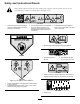
Safety and Instructional Decals Safety decals and instructions are easily visible to the operator and are located near any area of potential danger. Replace any decal that is damaged or lost. 107-2916 1. Remove the ignition key and read the Operator’s Manual before servicing or performing maintenance. 2. Thrown object hazard—do not operate the mower with the deflector up or removed, keep the deflector in place; keep bystanders a safe distance from the machine. 3.
99–5172 107-2915 1. 100-6578 1. Entanglement hazard, shaft—tykeep bystanders a safe distance from the machine. Entanglement hazard, belt—do not operate the machine with the shields or guards removed; always keep the shields and guards in place; stay away from moving parts. 107-2926 1. 2. Cutting/dismemberment hazard, impeller—stay away from moving parts. Thrown object hazard—keep bystanders a safe distance from the machine. 105–9553 1. 2. 93–7301 Warning—read the Operator’s Manual.
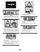
Setup Loose Parts Use the chart below to verify that all parts have been shipped. Procedure Description Use Qty. Front castor wheel assembly Rear castor wheel assembly Right-hand lift arm Left-hand lift arm Pivot pin Cotter pin (5/32 x 1-3/4 inches) 2 2 1 1 2 2 3 No parts required – Connect the lift arms to the cutting unit. 4 No parts required – Mount the PTO shaft guard and connect the PTO shaft to the cutting unit gear box. 5 No parts required – Install the rear weight.
3. Slide a thrust washer onto the spindle, push the round castor spindle through the front castor arm, and the hex castor spindle through the rear castor arm. 4. Install another thrust washer and the remaining spacers onto the spindle and install the tensioning cap to secure the assembly. Important: The thrust washers, not the spacers, must contact the top and bottom of the castor arm. 5. Ensure that all four castor wheels are set at the same height-of-cut and roll the cutting unit off of the pallet.
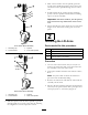
Figure 4 1. 2. Pivot pin Lift arm 3. 4. Lift arm pivot bracket Brake return spring Figure 5 1. 2. 5. Mount the rear of the lift arm to the lift cylinder with a pivot pin and 2 cotter pins (supplied with the traction unit). Lift arm Ball joint 3. 4. Jam nut 2–1/4 inch (57 mm) 3. Move the lift lever to the Float position. Push the lift arms down until the holes in the ball joint mounts lineup with the holes in the castor arms. 6. Hook the brake return spring to the hole in the lift arm (Figure 4).
4 5 Mounting the PTO Shaft Guard and Connecting the PTO Shaft to the Cutting Unit Gear Box Installing the Rear Weight No Parts Required Procedure No Parts Required Two Wheel Drive Groundsmaster 1000 and 200 Series traction units comply with CEN standard EN 836:1997, ISO standard 5395:1990 and the ANSI B71.4-2004 Standard when equipped with rear weight. Refer to the chart in the traction unit Operator’s Manual to determine the combinations of weight required.
Product Overview Operation Specifications Note: Determine the left and right sides of the machine from the normal operating position. Note: Specifications and design are subject to change without notice. Adjusting the Height-of-Cut Width of 61-5/8 inches (1.56 m) Cut The height-of-cut is adjustable from 1 to 4 inches (25 to 102 mm) in 1/2 inch (13 mm) increments, by adding or removing an equal number of spacers on the front and rear castor forks.
Adjusting the Rollers and Gage Wheel 2. Remove the washer from the spindle shaft. 3. Slide the spacers onto the spindle shaft to get the desired height-of-cut, then slide the washer onto the shaft. 4. Push the castor spindle through the front castor arm. Note: If the cutting unit is to be used in the 1 inch (25 mm) or 1-1/2 inches (38 mm) height-of-cut setting, the cutting unit rollers must be repositioned in the top bracket holes. 5.
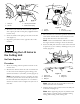
Adjusting the Rear (Internal) Rollers 1. Remove the cotter pins securing the roller shafts to the brackets on the underside of the deck (Figure 12). Figure 13 1. Dipstick/fill plug Figure 12 1. Internal rollers Greasing the Cutting Unit Before the cutting unit is operated, it must be greased to ensure proper lubricating characteristics; refer to Lubrication Section of Manual. Failure to properly grease the cutting unit will result in premature failure of critical parts. 2.
Note: The deflector is spring loaded into its downward normal operating position (Figure 14), but the operator can temporarily swing it out of the way to facilitate loading in a trailer or when otherwise necessary. Figure 14 1. Grass deflector 2.
Maintenance • blade spindle bearings (Figure 17) Lubrication The cutting unit must be lubricated regularly. If the machine is operated under normal conditions, lubricate the castor bearings and bushings with No. 2 general purpose lithium base grease or molybdenum base grease after every 8 hours of operation or daily, whichever comes first. All other bearings, bushings, and the gear box must be lubricated after every 50 hours of operation. Figure 17 1.
4. Remove the capscrews and locknuts securing the ball joint mounts to the castor arms on the cutting unit (Figure 19). 3. Slide the male PTO shaft into the female PTO shaft (Figure 20). 4. Move the lift lever to the Float position. Push the lift arms down until the holes in the ball joint mounts lineup with the holes in the castor arms (Figure 19). 5. Secure the ball joint mounts to the castor arms with the capscrews and flange nuts.
9. Push the castor shaft through the bushings and mounting tube. 10. Slide the thrust washer and spacer(s) onto the spindle. 11. Install the tensioning cap on the castor spindle to retain all of the parts in place. 5. Remove the bushing from the opposite side of the wheel hub. 6. Check the bearing, spanner, and inside of the wheel hub for wear, and replace any damaged parts. 7. To assemble the castor wheel, push the bushing into the wheel hub. 8. Slide the bearing into the wheel hub. 9.
Inspecting and Sharpening the Blade genuine Toro replacement blades to ensure safety and optimum performance. Never use blades made by other manufacturers because they could be dangerous. Two areas must be considered when checking and servicing the cutting blade: the sail and the cutting edge. Both cutting edges and the sail, which is the turned up portion opposite the cutting edge, contribute to a good quality-of-cut.
3. Raise the height-of-cut to the 4 inches (102 mm) position; refer to Adjusting the Height-of-Cut. 4. Rotate the blades so that the tips line up with one another. If the blade is allowed to wear, a slot will form between the sail and flat part of the blade (Figure 25). Eventually, a piece of the blade may break off and be thrown from under the housing, possibly resulting in serious injury to yourself or bystanders. Note: The tips of the adjacent blades must be within 1/8 inch (3 mm) of each other.
Note: To raise or lower the blade, add a shim, Part No. 3256-24, between the spindle housing and bottom of the cutting unit. Note: The deflector must be held firmly in the full downward position by the spring tension. Correct it if necessary. 11. Continue checking the alignment of the blades and adding shims until the tips of the blades are within the required dimension. Adjusting the Idler Pulley The idler pulley applies force against the belt so that power can be transmitted to the blade pulleys.
Replacing the Drive Belt The blade drive belt, tensioned by the adjustable idler, is very durable. However, after many hours of use, the belt will show signs of wear. Signs of a worn belt are: squealing when belt is rotating, blades slipping when cutting grass, frayed edges, burn marks, and cracks. Replace the belt if any of these conditions are evident. Important: The fasteners on the covers of this machine are designed to remain on the cover after removal.
Troubleshooting Problem The cutting unit will not cut or cuts poorly. Possible Cause Corrective Action 1. The blades are dull. 1. Sharpen the blades. 2. One or more blades are bent or damaged. 3. The spindle bolts are loose. 2. Replace the blades. 4. The cutting unit belts are loose or broken. 5. The gear box pulley is loose. 6. A gear box shaft is broken. 7. The PTO belt is broken. 8. The PTO pulley is loose or broken. 9. The PTO shaft is broken. 10.
Toro General Commercial Products Warranty A Two-Year Limited Warranty Conditions and Products Covered The Toro Company and its affiliate, Toro Warranty Company, pursuant to an agreement between them, jointly warrant your Toro Commercial Product (“Product”) to be free from defects in materials or workmanship for two years or 1500 operational hours*, whichever occurs first. This warranty is applicable to all products with the exception of Aerators (refer to separate warranty statements for these products).