Form No. 3383-259 Rev A 62in Side Discharge Mower Groundsmaster® 200, 3320 and 3280-D Series Traction Unit Model No. 30551—Serial No. 314000001 and Up Register at www.Toro.com.
Figure 1 Introduction 1. Safety alert symbol This product complies with all relevant European directives, for details please see the separate product specific Declaration of Conformity (DOC) sheet. This manual uses 2 other words to highlight information. Important calls attention to special mechanical information and Note emphasizes general information worthy of special attention.
Contents Introduction .................................................................. 2 Safety ........................................................................... 4 Safe Operating Practices........................................... 4 Toro Mower Safety .................................................. 5 Safety and Instructional Decals. ................................ 7 Setup ............................................................................ 9 1 Installing the Castor Wheel Assemblies .
Safety • Extinguish all cigarettes, cigars, pipes, and other sources This machine meets or exceeds CEN standard EN 836:1997, ISO standard 5395:1990, and ANSI B71.4-2012 specifications in effect at the time of production. • Use only an approved fuel container. • Never remove fuel cap or add fuel with the engine Improper use or maintenance by the operator or owner can result in injury.
Hauling • Look behind and down before backing up to be sure of a clear path. • Use care when loading or unloading the machine into a • Never carry passengers and keep pets and bystanders away. • • Slow down and use caution when making turns and crossing roads and sidewalks. Stop blades if not mowing. • • Do not operate the mower under the influence of alcohol or drugs. • Lightning can cause severe injury or death. If lightning trailer or truck.
• Make sure that all hydraulic line connectors are tight and all hydraulic hoses and lines are in good condition before applying pressure to the system. • Keep your body and hands away from pin hole leaks or nozzles that eject hydraulic fluid under high pressure. Use paper or cardboard, not your hands, to search for leaks. Hydraulic fluid escaping under pressure can have sufficient force to penetrate the skin and cause serious injury.
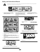
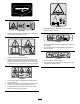
Safety and Instructional Decals. Safety decals and instructions are easily visible to the operator and are located near any area of potential danger. Replace any decal that is damaged or lost. 107-2916 1. Remove the ignition key and read the Operator's Manual before servicing or performing maintenance. 2. Thrown object hazard—do not operate the mower with the deflector up or removed, keep the deflector in place; keep bystanders a safe distance from the machine. 3.
99–5172 107-2915 1. Entanglement hazard, shaft-keep bystanders a safe distance from the machine. 117–4979 1. Entanglement hazard, belt—stay away from moving parts, keep all guards and shields in place. 107-2926 1. Cutting/dismemberment hazard, impeller—stay away from moving parts. 2. Thrown object hazard—keep bystanders a safe distance from the machine. 105–9553 1. Warning—read the Operator's Manual. 93–7301 2. Tipping hazard—lower the cutting unit when driving down slopes.
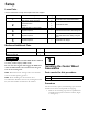
Setup Loose Parts Use the chart below to verify that all parts have been shipped. Procedure Description Use Qty. Front castor wheel assembly Rear castor wheel assembly Right-hand lift arm Left-hand lift arm Pivot pin Cotter pin (5/32 x 1-3/4 inches) 2 2 1 1 2 2 3 No parts required – Connect the lift arms to the cutting unit. 4 No parts required – Mount the PTO shaft guard and connect the PTO shaft to the cutting unit gear box. 5 No parts required – Install the rear weight.
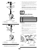
3. Slide a thrust washer onto the spindle, push the round castor spindle through the front castor arm, and the hex castor spindle through the rear castor arm. 4. Install another thrust washer and the remaining spacers onto the spindle and install the tensioning cap to secure the assembly. Important: The thrust washers, not the spacers, must contact the top and bottom of the castor arm. 5. Ensure that all four castor wheels are set at the same height-of-cut and roll the cutting unit off of the pallet.
5. Mount the rear of the lift arm to the lift cylinder with a pivot pin and 2 cotter pins (supplied with the traction unit). 4. Secure the ball joint mounts to each castor arm with 2 capscrews (7/16 x 3 inches) and flange nuts (7/16 inches) (Figure 6). 6. Hook the brake return spring to the hole in the lift arm (Figure 4). 7. Repeat the procedure on the opposite side of the machine. 3 Connecting the Lift Arms to the Cutting Unit No Parts Required Figure 6 Procedure 1. Castor arm 4. Capscrew 2.
Two Wheel Drive Groundsmaster 3280-D and Groundsmaster 3320 traction units with serial numbers 260000101 and up do not need additional rear weight to comply with CEN standard EN 836:1997, ISO standard 5395:1990 and the ANSI B71.4-2012 Standard. Four Wheel Drive Groundsmaster 3280-D traction units do not need additional rear weight to comply with CEN standard EN 836:1997, ISO standard 5395:1990 and the ANSI B71.4-2012 Standard. Figure 7 1. PTO guard 2.
Product Overview Operation Specifications. Note: Determine the left and right sides of the machine from the normal operating position. Note: Specifications and design are subject to change without notice. Adjusting the Height-of-Cut Width of Cut 1.56 m (61-5/8 inches) Height of Cut Adjustable from 25 to 102 mm (1 to 4 inches) in 13 mm (1/2 inch) increments Blade Tip Speed 15,480 ft/minute @ 3250 engine RPM Cutting Blades 3 heat-treated steel blades, each 4.
Adjusting the Rollers and Gage Wheel 2. Remove the washer from the spindle shaft. 3. Slide the spacers onto the spindle shaft to get the desired height-of-cut, then slide the washer onto the shaft. Note: If the cutting unit is to be used in the 25 mm (1 inch) or 38 mm (1-1/2 inches) height-of-cut setting, the cutting unit rollers must be repositioned in the top bracket holes. 4. Push the castor spindle through the front castor arm. 5.
Adjusting the Rear (Internal) Rollers Greasing the Cutting Unit 1. Remove the cotter pins securing the roller shafts to the brackets on the underside of the deck (Figure 12). Before the cutting unit is operated, it must be greased to ensure proper lubricating characteristics; refer to Lubrication Section of Manual. Failure to properly grease the cutting unit will result in premature failure of critical parts.
Maintenance • Blade spindle bearings (Figure 17) Lubrication The cutting unit must be lubricated regularly. If the machine is operated under normal conditions, lubricate the castor bearings and bushings with No. 2 general purpose lithium base grease or molybdenum base grease after every 8 hours of operation or daily, whichever comes first. All other bearings, bushings, and the gear box must be lubricated after every 50 hours of operation. Figure 17 1.
4. Move the lift lever to the Float position. Push the lift arms down until the holes in the ball joint mounts lineup with the holes in the castor arms (Figure 19). 5. Secure the ball joint mounts to the castor arms with the capscrews and flange nuts. 4. Remove the capscrews and locknuts securing the ball joint mounts to the castor arms on the cutting unit (Figure 19).
Servicing the Castor Wheels and Bearings 9. Push the other bushing into the open end of the wheel hub to captivate the bearing inside the wheel hub (Figure 22). 10. Carefully slide the spanner through the bushings and the wheel hub. The castor wheel rotates on a high-quality roller bearing and is supported by a spanner bushing. Even after many hours of use, provided that the bearing was kept well lubricated, bearing wear will be minimal.
producing an even cut. However, the sail will gradually wear down during operation, and this condition is normal. As the sail wears down, the quality-of-cut will degrade somewhat, although the cutting edges are sharp. The cutting edge of the blade must be sharp so that the grass is cut rather than torn. A dull cutting edge is evident when the tips of the grass appear brown and shredded. Sharpen the cutting edges to correct this condition.
Note: Sharpen only the top side of the cutting edge and maintain the original cutting angle to ensure sharpness (Figure 26). The blade will remain balanced if the same amount of metal is removed from both cutting edges. B B B A A C A C C G010556 Figure 27 Figure 26 1. Sharpen at original angle 1 Note: Remove the blades and sharpen them on a grinder; refer to Removing the Cutting Blades. G010557 Figure 28 1. Measure from the blade tip to a level surface. 6.
position, shut the engine off, and remove the ignition key. 3. Remove the cover from the center cutting unit. 4. Loosen the 2 nuts that secure the idler plate in place. 5. Use a socket and torque wrench to tighten the idler adjusting nut to 47 to 54 N-m (35 to 40 ft-lb) (Figure 30). Figure 29 1. Bolt 2. Locknuts 3. Pivot brackets 4. Spring 5. To remove the pivot brackets, remove the carriage bolts and nuts (Figure 29). 6.
5. To install a new belt, you must remove the gear box by removing the 4 carriage bolts and locknuts holding the gear box base. 6. Install the new belt around the gear box pulley, spindle pulleys, stationary idler pulley, and adjustable idler pulley (Figure 31). 1 2 G010560 Figure 31 1. Adjustable idler pulley 2. Gear box pulley 7. Install the gear box base with the carriage bolts and locknuts. 8.
Troubleshooting Problem The cutting unit will not cut or cuts poorly. Possible Cause Corrective Action 1. The blades are dull. 1. Sharpen the blades. 2. One or more blades are bent or damaged. 3. The spindle bolts are loose. 2. Replace the blades. 4. The cutting unit belts are loose or broken. 5. The gear box pulley is loose. 6. A gear box shaft is broken. 7. The PTO belt is broken. 8. The PTO pulley is loose or broken. 9. The PTO shaft is broken. 10.
Notes: 24
Notes: 25
Notes: 26
Declaration of Incorporation The Toro Company, 8111 Lyndale Ave. South, Bloomington, MN, USA declares that the following unit(s) conform(s) to the directives listed, when installed in accordance with the accompanying instructions onto certain Toro models as indicated on the relevant Declarations of Conformity. Model No. 30551 Serial No.
The Toro Total Coverage Guarantee A Limited Warranty Conditions and Products Covered The Toro Company and its affiliate, Toro Warranty Company, pursuant to an agreement between them, jointly warrant your Toro Commercial product (“Product”) to be free from defects in materials or workmanship for two years or 1500 operational hours*, whichever occurs first. This warranty is applicable to all products with the exception of Aerators (refer to separate warranty statements for these products).