Form No. 3350–322 Rev B 62, Side Discharge Mower Groundsmaster) 200 Series, 3280–D & 3320 Model No. 30551—Serial No.
Contents Introduction Page Introduction . . . . . . . . . . . . . . . . . . . . . . . . . . . . . . . . 2 Safety . . . . . . . . . . . . . . . . . . . . . . . . . . . . . . . . . . . . . 3 Safe Operating Practices . . . . . . . . . . . . . . . . . . . . 3 Toro Mower Safety . . . . . . . . . . . . . . . . . . . . . . . . 4 Safety and Instruction Decals . . . . . . . . . . . . . . . . 6 Specifications . . . . . . . . . . . . . . . . . . . . . . . . . . . . . . . 8 General Specifications . . . . . . . . . .
Safety – Never remove fuel cap or add fuel with engine running. Allow engine to cool before refueling. Do not smoke. This machine meets or exceeds CEN standard EN 836:1997, ISO standard 5395:1990, and ANSI B71.4-1999 specifications in effect at the time of production. – Never refuel or drain the machine indoors. • Check that operator’s presence controls, safety switches and shields are attached and functioning properly. Do not operate unless they are functioning properly.
Operation • The operator shall turn on flashing warning lights, if provided, whenever traveling on a public road, except where such use is prohibited by law. • Know how to stop the machine and engine quickly. • Always wear substantial shoes. Do not operate the machine while wearing sandals, tennis shoes, or sneakers. Maintenance and Storage • Disengage drives, lower the cutting units, move traction pedal to Neutral, set parking brake, stop engine and remove key and disconnect spark plug wire.
• Before disconnecting or performing any work on the hydraulic system, all pressure in the system must be relieved by stopping the engine and lowering the cutting units to the ground. • If the engine must be running to perform a maintenance adjustment, keep hands, feet, clothing, and any parts of the body away from the cutting units, attachments, and any moving parts. Keep everyone away. • Do not overspeed the engine by changing governor settings.
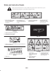
Safety and Instruction Decals Safety decals and instructions are easily visible to the operator and are located near any area of potential danger. Replace any decal that is damaged or lost. 107-2916 1. Remove the ignition key and read the instructions before servicing or performing maintenance. 2. Do not operate the mower with the deflector up or removed; keep the deflector in place. 3. Thrown object hazard—keep bystanders a safe distance from the machine. 4.
106-6753 1. Thrown object hazard—keep bystanders a safe distance from the machine. 107-2915 2. Cutting/dismemberment hazard of hand or foot, mower blade—stay away from moving parts. 1. Entanglement hazard, shaft—keep bystanders a safe distance from the machine. 93-6697 1. Read the operator’s manual for further information on lubrication. 105-9553 1. Warning—read the Operator’s Manual. 2. Tipping hazard—lower the cutting unit when driving down slopes. Add a 25 kg (55 lb.
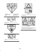
Specifications General Specifications Width of Cut 61-5/8 in. (1.56 m) Height of Cut Adjustable from 1 to 4 in. (25 to 102 mm) in 1/2 inch increments Blade Tip Speed Cutting Blades Unit Drive System Castor Wheels 15,480 ft./min. @ 3250 engine RPM 3 heat-treated steel blades, each 3/16 in. (4.8 mm) thick and 24-3/4 in. (55 cm) long PTO driven gear box transmits power through a “AA” section belts to all blade spindles. 8 in.
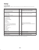
Setup Loose Parts Note: Use this chart as a checklist to ensure that all parts have been received. Without these parts, total setup cannot be completed. Description Qty. Front castor wheel assembly 2 Rear castor wheel assembly 2 Right-hand lift arm 1 Left-hand lift arm 1 Pivot pin assembly 2 Cotter pin, 5/32 in. x 1-3/4 in.
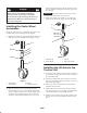
Install another thrust washer and the remaining spacers onto the spindle and install the tensioning cap to secure the assembly. Danger If the engine is started and the PTO shaft is allowed to rotate, serious injury could result. Important The thrust washers, not the spacers, must contact the top and bottom of the castor arm. Do not start the engine and engage the PTO lever when the PTO shaft is not connected to the gear box on the cutting unit. 3.
3. Move the lift lever to the Float position. Push the lift arms down until the holes in the ball joint mounts line up with the holes in the castor arms. 2 Note: On the Groundsmaster 3280–D and 3320 the engine must be running to lower the lift arms. 4. Secure the ball joint mounts to each castor arm with 2 capscrews (7/16 x 3 in.) and flange nuts (7/16 in.) (Fig. 5). 1 Note: The ball joint mount should be above the castor arm when it is assembled. 4 3 5.
Mounting the PTO Shaft Guard and Connecting the PTO Shaft to the Cutting Unit Gear Box 1. Remove the 2 capscrews and lock washers securing the PTO guard mounting brackets to the gearbox (Fig. 6). Retain the fasteners for future installation. 2. Slide the PTO shaft guard onto the PTO shaft, positioning the guard as shown in Figure 6. 3 2 1 4 3 Figure 7 1. 52″ side discharge deck 2. 52″ deck w/bagger 2 3. 62″ and 72″ decks 4. 52″ rear discharge deck 3.
6. Mount the bottom of the knee link to the deck bracket with a shoulder bolt and locknut. Use the heavy rate extension on the left-hand side (large diameter spring wire) and the light rate extension spring on the right, discharge side (small diameter spring wire). 1 7. Align the slotted holes in the spring cover (slot toward the bottom) with the mounting bracket holes. Insert the lock pin assemblies into the bracket holes and secure each to the bracket with the self-tapping screws (Fig. 9).
Installing Rear Weight Start the engine and raise the cutting unit so that the height-of-cut can be changed. Stop the engine after the cutting unit is raised. Two Wheel Drive Groundsmaster 1000 and 200 Series traction units comply with CEN standard EN 836:1997, ISO standard 5395:1990 and the ANSI B71.4-2004 Standard when equipped with rear weight. Refer to the chart in the traction unit Operator’s Manual to determine the combinations of weight required.
2 3 4 4 2 1 Figure 14 1. External roller 2. Roller shaft 1 Adjusting the Front Gage Wheel Figure 13 1. Rear castor wheel 2. Tensioning cap 1. Remove the capscrew and nut securing the gage wheel to the cutting unit brackets (Fig. 15). 3. Spacers 4. Thrust washers 2. Align the roller and spacer with the top holes in the brackets and secure them with the capscrew and nut. 2.
Operation 3. Install the cotter pins to secure the assemblies. Note: Determine the left and right sides of the machine from the normal operating position. Using the Grass Deflector Danger Without the grass deflector mounted in place, you and others are exposed to blade contact and thrown debris. Contact with the rotating mower blade(s) and thrown debris will cause injury or death. 1 Figure 16 1.
Adjusting the Tension Spring Note: Only when cutting unit is installed on a Groundsmaster 200 Series traction unit. For best performance, the cutting unit bounce on uneven turf is minimal and it does not ride heavily over flat terrain. If scalping occurs or the cut is uneven from side to side, there may too much weight on the deck and weight may have to be transferred to the traction unit: i.e. increased spring tension.
Maintenance Note: Determine the left and right sides of the machine from the normal operating position. Recommended Maintenance Schedule Maintenance Service Interval Maintenance Procedure After first 2 hours • Tighten the castor wheel nuts. After first 10 hours • Tighten the castor wheel nuts. • Torque the blade bolts. Daily • Check the blades. • Lubricate the castor arm bushings. • Lubricate the castor wheel bearings. Tighten the castor wheel nuts. Torque the blade bolts.
Separating the Cutting Unit from the Traction Unit 1. Position the machine on a level surface, raise the cutting unit, engage the parking brake, put the traction pedal in neutral, the PTO lever in the Off position, shut the engine off, and remove the ignition key. Caution On Groundsmaster 200 Series traction units the counterbalance spring is in tension when the deck is in the lowered position.
4. Move the lift lever to the Float position. Push the lift arms down until the holes in the ball joint mounts line up with the holes in the castor arms (Fig. 24). 2 5. Secure the ball joint mounts to the castor arms with the capscrews and flange nuts. 1 6. Raise the cutting unit and place blocks under it to prevent it from falling during assembly. 7. Connect the counterbalance to the traction unit brackets with lock pins (Fig. 23). 8. Remove the blocks from under the cutting unit.
Servicing the Castor Wheels and Bearings 7. Install the castor wheel assembly between the castor fork and secure it in place with the capscrew, washers, and locknut. The castor wheel rotates on a high-quality roller bearing and is supported by a spanner bushing. Even after many hours of use, provided that the bearing was kept well lubricated, bearing wear will be minimal. However, failure to keep the bearing lubricated will cause rapid wear. A wobbly castor wheel usually indicates a worn bearing. 8.
2. Examine the cutting ends of the blade carefully, especially where the flat and curved parts of the blade meet (Fig. 30-A). Since sand and abrasive material can wear away the metal that connects the flat and curved parts of the blade, check the blade before using the machine. If wear is noticed (Fig. 30-B), replace the blade; refer to Removing the Cutting Blade, page 21. 1.
SHARPEN AT THIS ANGLE ONLY B B B A END VIEW A Figure 31 Note: Remove the blades and sharpen them on a grinder; refer to Removing the Cutting Blades, page 21, steps 1 and 2. After sharpening the cutting edges, install the blade with the anti-scalp cup and blade bolt. The blade sails must be on top of the blade. Tighten the blade bolt to 85–110 ft.-lb. (115–149 N⋅m). C A C C Figure 32 6. Note the measurement attained at “A”, rotate the blades to the “B” position (Fig.
Replacing the Grass Deflector large nut, which applies force against the belt. If the idler is not adjusted to these specifications, an adjustment is necessary. 1. Position the machine on a level surface, raise the cutting unit, engage the parking brake, put the traction pedal in neutral, the PTO lever in the Off position, shut the engine off, and remove the ignition key. Block the cutting unit to prevent it from accidentally falling. 1.
2. Release and unhook the latches securing the covers to the top of the cutting unit. Remove the covers. 3. Loosen the 2 nuts securing the idler plate in place and remove the old belt from the pulleys. 4. To install a new belt, the gear box base must be removed. To do this, remove the 4 carriage bolts and locknuts holding the gear box base. 5. Install the new belt around the gear box pulley, spindle pulleys, stationary idler pulley, and adjustable idler pulley (Fig. 36). 2 1 Figure 36 1.
BROKEN REPLACE LOOSE OR BROKEN REPLACE TIGHTEN OR REPLACE LOOSE OR BROKEN INSPECT P.T.O. PULLEY INSPECT P.T.O. SHAFT INSPECT PULLEY ON ENGINE OUTPUT SHAFT OK TIGHTEN OR REPLACE RETORQUE 85 TO 110 FOOT POUNDS SHARPEN OR REPLACE OK LOOSE OR BROKEN BELTS INSPECT CUTTER DECK LOOSE OK DULL OR BENT INSPECT SPINDLE BOLTS OK BLADES INSPECT CUTTER OK OK REPLACE BROKEN BELT INSPECT P.T.O.
The Toro General Commercial Products Warranty A Two-Year Limited Warranty Conditions and Products Covered The Toro Company and its affiliate, Toro Warranty Company, pursuant to an agreement between them, jointly warrant your Toro Commercial Product (“Product”) to be free from defects in materials or workmanship for two years or 1500 operational hours*, whichever occurs first.