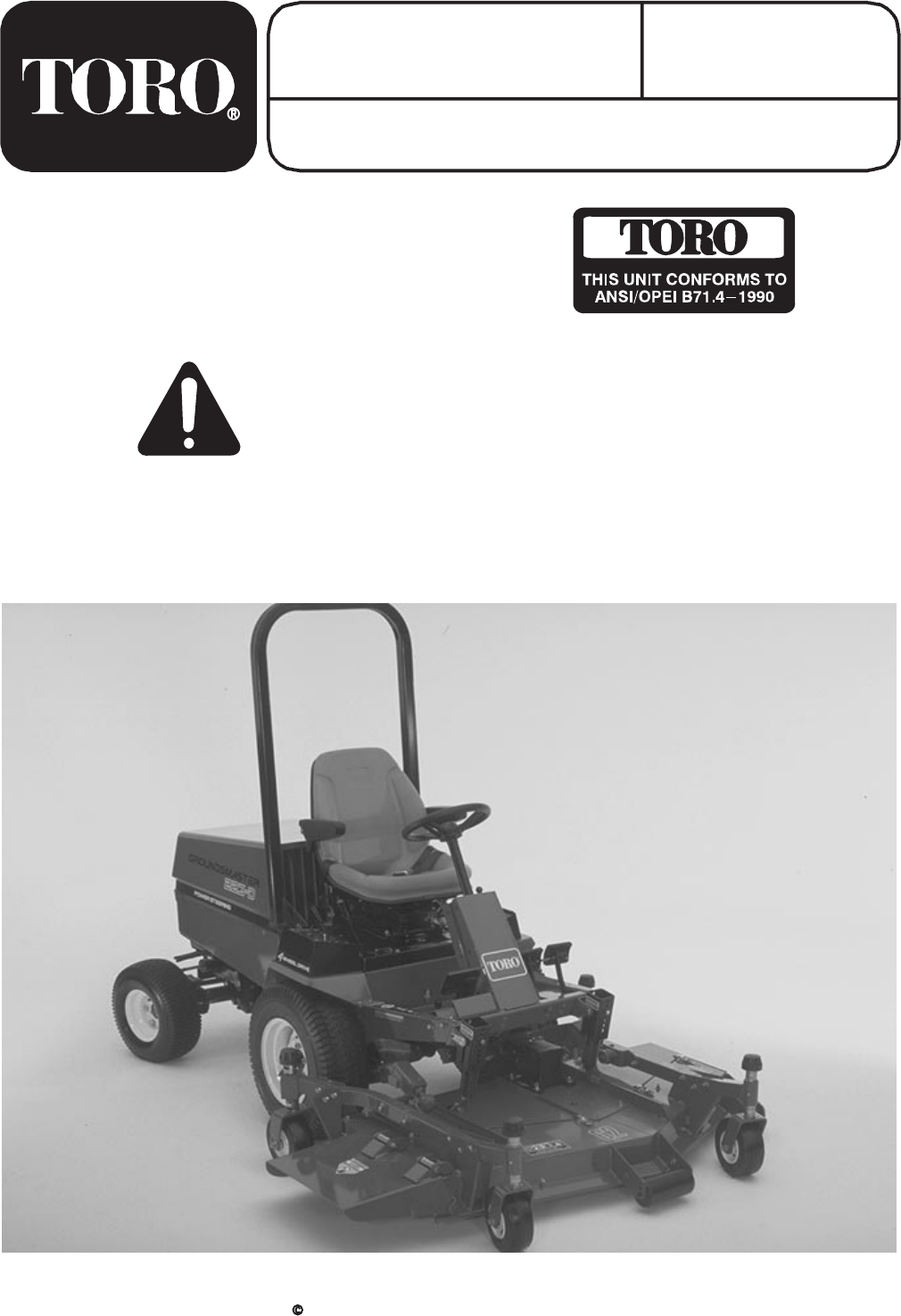
FORM NO. 3326-147 MODEL NO. 30551 - 210000001 & UP OPERATOR'S MANUAL 62" SIDE DISCHARGE CUTTING DECK FOR GROUNDSMASTER 200 SERIES TRACTION UNITS To assure maximum safety, optimum performance, and to gain knowledge of the product, it is essential that you or any other operator of the machine read and understand the contents of this manual before the engine is ever started.
FOREWORD The 62" cutting deck has advanced concepts in engineering, design and safety; and if maintained properly, will give excellent service. Since this is a high-quality product, Toro is concerned about the future use of the machine and safety of the user. Therefore, read this manual to familiarize yourself with proper set-up, operation and maintenance instructions. The major sections of the manual are: 1. Safety Instructions 2. Set-up Instructions 3. Before Operating 4. Lubrication 5.
SAFETY INSTRUCTIONS The safety alert symbol means CAUTION, WARNING or DAN GER personal safety instruction". Read and under stand the instruction because it has to do with safety. Failure to comply with the instruction may result in personal injury. The cutting unit has been tested and certified for compliance with the B71.4-1990 specifications of the American National Standards Institute.
SAFETY INSTRUCTIONS F. Before backing up, look to the rear and assure no one is behind the machine. G. Watch out for traffic when near or crossing roads. Always yield the right-of -way. H. The cutting deck must be lowered when going down slopes for steering control. 14. The grass deflector must always be installed and in lowest position on the side discharge cutting unit. Never operate mower without deflector or entire grass collector.
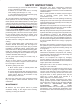
SAFETY AND INSTRUCTION DECALS The following decals are installed on the machine. If any become damaged or illegible, replace it. The decal part number is listed below and in your parts catalog. Replacement can be ordered from your Authorized Toro Distributor. ON BOTH SIDES OF CUTTING UNIT (Part No. 93-7824) ON LEFT SIDE OF CASTOR ARM (Part No. 92-3035) UNDER DEFLECTOR (Part No. 100-6553) ON LEFT SIDE OF CUTTING DECK (Part No. 100-6582) ON LEFT SIDE OF CUTTING UNIT (Part No.
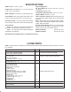
SPECIFICATIONS Width of Cut: 61-5/8 in. (1.56 m). Height of Cut: Adjustable from 1" to 4" (25 to 102 mm) in 1/2" (13 mm ) increments. Blade Tip Speed: 15,480 ft/min. @ 3250 engine rpm. Cutter Blades: Three heat treated steel blades, each 3/16 in. (4.8 mm) thick and 24-3/4" (55 mm) long. Unit Drive System : PTO driven gear box transmits power through a AA" section belt to all blade spindles. Castor Wheels: Front - 8 in. (203 mm) dia. pneumatic wheels with greaseable roller bearings. (Inflation 35-50 P.S.I.
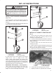
SET-UP INSTRUCTIONS DANGER 1 Do not start the engine and engage the PTO lever when PTO shaft is not connected to cut ting unit gear box because the PTO shaft will rotate with enough force to cause serious in jury. INSTALL CASTOR WHEEL ASSEMBLIES (Fig. 1 & 2) 3 2 4 2 The thrust washers, spacers and tensioning caps have been installed on the castor wheel spindles for shipping. 1. Remove tensioning caps from spindle shafts and slide off spacers and thrust washers. 1 3 1. Tensioning cap 2.
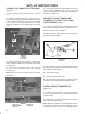
SET-UP INSTRUCTIONS CONNECT LIFT ARMS TO CUTTING UNIT (Fig. 4-5) 1. Move cutting unit into position in front of traction unit. 2. Measure distance from end of each lift arm to center of ball joint (grease fitting). Distance should be 2.25". If distance is not 2.25", loosen jam nut securing ball joint to lift arm and rotate ball joint in or out until distance is attained. Do not tighten jam nuts at this time. 1 3 5. Tighten large jam nut securing ball joint to lift arm (FIg. 5).
SET-UP INSTRUCTIONS 6. Mount bottom of knee link to deck bracket with a shoulder bolt and locknut. Use the heavy rate extension on the left hand side (large diameter spring wire) and the light rate extension spring on the right, discharge side (small diameter spring wire). 3 2 1 4 3 7. Align slotted holes in the spring cover (slot toward the bottom) with the mounting bracket holes. Insert lock pin assemblies into the bracket holes and secure each to the bracket with self-tapping screws (Fig. 9).
SET-UP INSTRUCTIONS 8. From the bottom, insert the spring and top spring end into the spring cover. Select a hole that matches the cutter deck height-of-cut setting; i.e., top cover hole matches the highest height setting, bottom cover hole the lowest, etc. Align the top spring end hole with the selected spring cover holes and insert the clevis pin to secure the spring inside the cover (Fig. 9). Secure clevis pin with a hair pin cotter. 1 2 9. Remove the blocks from under the cutting unit.
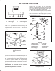
BEFORE OPERATING ADJUSTING HEIGHT-OF-CUT (Fig. 12-13) The height-of-cut is adjustable from 1 to 4 inches in 1/2 inch increments, by adding or removing an equal number of spacers from the front and rear castor forks. The height-of-cut chart below gives the combinations of spacers to use for all height-of-cut settings. Height-of-Cut Chart Height-of-Cut Spacers Below Castor Arm Setting Front Rear 1 inch 0 0 1-1/2 inch 1 1 2 inch 2 2 2-1/2 inch 3 3 3 inch 4 4 3-1/2 inch 5 5 4 inch 6 6 1.
BEFORE OPERATING 1 1 2 Figure 16 Figure 14 1. Internal rollers 1. External Roller 2. Roller Shaft CHECK LUBRICANT IN GEAR BOX (Fig. NO TAG) To adjust front gage wheel (Fig. 15): 1. Remove capscrew and nut securing gage wheel to cutting unit brackets. 2. Align roller and spacer with top holes in brackets and secure with capscrew and nut. The gear box in designed to operate on SAE 80-90 wt. gear lube.
OPERATING INSTRUCTIONS GRASS DEFLECTOR (Fig. 18) TENSION SPRING ADJUSTMENT WARNING The grass deflector (Fig. 18) is a safety device that diverts grass and other foreign objects being discharged downward. WE STRONGLY RECOMMEND THAT THE DEFLECTOR BE IN ITS NORMAL OPERATING POSITION WHENEVER THE CUTTING UNIT IS ENGAGED. NEVER OPERATE CUTTING UNIT WITH THE DEFLECTOR REMOVED FROM THE CUTTING UNIT OR IT TIED/BLOCKED IN A RAISED POSITION.
LUBRICATION GREASE BEARINGS, BUSHINGS AND GEAR BOX (Fig. 19-22) The cutting unit must be lubricated regularly. If machine is operated under normal conditions, lubricate castor bearings and bushings with No. 2 general purpose lithium base grease or molybdenum base grease, after every 8 hours of operation or daily, whichever comes first 1. The cutting unit has bearings and bushings that must be lubricated, and these lubrication points are: front castor spindle bushings (Fig.
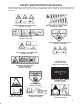
UNIT WILL NOT CUT OR CUTS POORLY INSPECT CUTTER OK INSPECT SPINDLE BOLTS DULL OR BENT LOOSE SHARPEN OR REPLACE INSPECT PULLEY ON ENGINE OUTPUT SHAFT RETORQUE 85 TO 110 FOOT POUNDS OK INSPECT P.T.O. SHAFT OK INSPECT CUTTER DECK OK INSPECT GEAR BOX OK INSPECT GEAR BOX BELTS PULLEY SHAFTS LOOSE OR BROKEN LOOSE BROKEN TIGHTEN OR REPLACE TIGHTEN OR REPLACE REPLACE INSPECT P.T.O. PULLEY OK INSPECT P.T.O.
MAINTENANCE SEPARATING CUTTING UNIT FROM TRACTION UNIT (Fig. 23-25) 5. Roll cutting unit away from the traction unit separating male and female sections of PTO shaft. 1. Position machine on a level surface, raise cutting unit, engage parking brake, be sure traction pedal is in neutral position, PTO lever in OFF position, shut engine OFF and remove key from switch. CAUTION Counterbalance spring(s) are in tension when deck is in lowered position. Always raise deck before adjusting or removing spring(s). 2.
MAINTENANCE SERVICING CASTOR ARM BUSHINGS (Fig. 26) The castor arms have bushings pressed into the top and bottom of the tube and after many hours of operation, the bushings will wear. To check the bushings, move castor fork back and forth and from side to side. If castor spindle is loose inside the bushings, bushings are worn and must be replaced. 1. Raise cutting unit so wheels are off floor and block it so it cannot fall accidentally. 2.
MAINTENANCE CHECKING FOR BENT BLADE (Fig. 28) 1. Position machine on a level surface, raise cutting unit, engage parking brake, be sure traction pedal is in neutral position, PTO lever in OFF position, shut engine OFF, remove key from switch and disconnect wires from spark plugs. Block cutting unit to prevent it from falling accidentally. 3 2. Rotate blade until the ends face forward and backward. Measure from inside of cutting unit to cutting edge at front of blade (Fig. 28), and remember this dimension.
MAINTENANCE CORRECTING CUTTING UNIT MISMATCH (Fig. 32-33) If one cutter blade cuts lower than the others, correct as follows: A 1. Lower cutting unit onto a level surface, engage parking brake, be sure traction pedal is in neutral position, PTO lever in OFF position, shut engine OFF, remove key from switch and disconnect wires from spark plugs. Make sure tire pressure is equal on all tires. B 2. Raise height-of-cut to the 4 in. position: refer to Adjusting Height-Of-Cut. C 3.
MAINTENANCE 8. Compare measurements at various positions. All dimensions must be equal within 1/4 in. from any two adjacent blades. The difference between dimensions of all three blades must not exceed 3/8 in. If difference exceeds specifications proceed to step 9. 9. Remove capscrews, flatwashers and locknuts from outer spindle in the area where shims must be added. To raise or lower the blade, add a shim, Part No. 3256-24, between spindle housing and bottom of cutting unit.
MAINTENANCE 2. Release and unhook latches securing covers to top of cutting unit. Remove covers. 2 1 3. Loosen two nuts securing idler plate in place and remove old belt from pulleys. 4. To install new belt, the gear box base must be removed. To do this, remove four carriage bolts and locknuts holding gear box base. 5. Install new belt around gear box pulley, spindle pulleys, stationary idler pulley and adjustable idler pulley. 3 6. Install gear box base with carriage bolts and locknuts. 7.
IDENTIFICATION AND ORDERING MODEL AND SERIAL NUMBERS The cutting deck has two identification numbers: a model number and a serial number. The two numbers are stamped into a plate which is located on carrier frame behind the right front castor wheel. In any correspondence concerning the mower, supply the model and serial numbers to assure that correct information and replacement parts are obtained. 22 To order repIacement parts from an authorized TORO Distributor, supply the following information: 1.
NOTES 23
The Toro General Commercial Products Warranty A Two-Year Limited Warranty Conditions and Products Covered The Toro Company and its affiliate, Toro Warranty Company, pursuant to an agreement between them, jointly warrant your 1996 or newer Toro Commercial Product (“Product”) purchased after January 1, 1997, to be free from defects in materials or workmanship for two years or 1500 operational hours*, whichever occurs first.