Form No. 3350–815 72 Side Discharge Mower Groundsmaster 200 Series Model No. 30553—Serial No.
Contents Introduction . . . . . . . . . . . . . . . . . . . . . . . . . . . . . . . . . Safety . . . . . . . . . . . . . . . . . . . . . . . . . . . . . . . . . . . . . . Safe Operating Practices . . . . . . . . . . . . . . . . . . . . Toro Mower Safety . . . . . . . . . . . . . . . . . . . . . . . . Safety and Instruction Decals . . . . . . . . . . . . . . . . . Specifications . . . . . . . . . . . . . . . . . . . . . . . . . . . . . . . . General Specifications . . . . . . . . . . . . . . . . . . . . .
• Be sure all drives are in neutral and parking brake is engaged before starting engine. Only start engine from the operator’s position. Use seat belts if provided. Safe Operating Practices The following instructions are from the CEN standard EN 836:1997, ISO standard 5395:1990, and ANSI B71.4-1999. • Slow down and use extra care on hillsides. Be sure to travel in the recommended direction on hillsides. Turf conditions can affect the machine’s stability. Use caution while operating near drop-offs.
• Shut off fuel while storing or transporting. Do not store fuel near flames or drain indoors. • Check the safety interlock switches daily for proper operation. If a switch should fail, replace the switch before operating the machine. After every two years, replace all three interlock switches in the safety system, regardless if they are working properly or not. • Park machine on level ground. Never allow untrained personnel to service machine. • Pay attention when using the machine.
• The engine must be shut off before checking the oil or adding oil to the crankcase. • To make sure of optimum performance and continued safety certification of the machine, use only genuine Toro replacement parts and accessories. Replacement parts and accessories made by other manufacturers could be dangerous, and such use could void the product warranty. • Make sure that the mower fuel tank is empty if the machine is to be stored in excess of 30 days.
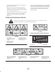
93-6697 1. Read the Operator’s Manual. 2. Add SAE 80w–90 (API GL-5) oil every 50 hours. 99-5172 100-6578 1. Entanglement hazard, belt—do not operate the machine with the shields or guards removed; always keep the shields and guards in place. Stay away from moving parts. 105-9554 1. Warning—read the Operator’s Manual. 2. Tipping hazard—lower the cutting unit when driving down slopes. For 2 wheel drive units, add a 41 kg (90 lb) rear weight to GM 228D units and a 63.
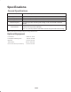
Specifications General Specifications Width of Cut 71-5/8 in. (1.82 m) Height of Cut Adjustable from 1 to 4 in. (25 to 102 mm) in 1/2 inch increments Blade Tip Speed Cutting Blades Unit Drive System Castor Wheels 16,270 ft./min. @ 3250 engine RPM 3 heat-treated steel blades, each 3/16 in. (4.8 mm) thick and 24-3/4 in. (55 cm) long PTO driven gear box transmits power through a “AA” section belts to all blade spindles. Front: 8 in.
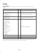
Setup Loose Parts Note: Use this chart as a checklist to ensure that all parts have been received. Without these parts, total setup cannot be completed. Description Qty. Front castor wheel assembly 2 Rear castor wheel assembly 2 Right-hand lift arm 1 Left-hand lift arm 1 Pivot pin assembly 2 Cotter pin, 5/32 in. x 1-3/4 in. 2 Capscrew, 7/16 x 3 in. 4 Flange nut, 7/16 in.
Install another thrust washer and the remaining spacers onto the spindle and install the tensioning cap to secure the assembly. Danger If the engine is started and the PTO shaft is allowed to rotate, serious injury could result. Important The thrust washers, not the spacers, must contact the top and bottom of the castor arm. Do not start the engine and engage the PTO lever when the PTO shaft is not connected to the gear box on the cutting unit. 3.
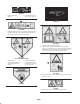
1 2 3 2-1/4 in. (57 mm) 1 4 3 Figure 3 1. Pivot pin 2. Lift arm 3. Lift arm pivot bracket 4. Brake return spring 2 Figure 4 6. Hook the brake return spring to the hole in the lift arm (Fig. 3). 1. Lift arm 2. Ball joint 7. Install the wheel and tire assembly. Torque the wheel nuts to 45–55 ft.-lb. (62–72 N⋅m). 3. Jam nut 3. Move the lift lever to the Float position. Push the lift arms down until the holes in the ball joint mounts line up with the holes in the castor arms. 8.
Connecting the PTO Shaft to the Cutting Unit Gear Box 1. Remove (2) capscrews and lockwashers securing PTO guard mounting brackets to gearbox (Fig. 6). Retain fasteners for re–installation. 2 3 2 1 4 3 Figure 7 1 1. 52″ side discharge deck 2. 52″ deck w/bagger 3 3. 62″ and 72″ decks 4. 52″ rear discharge deck 3. To install the mounting brackets, insert 2 flange head capscrews (3/8 x 1 in.) through the slotted bracket holes.
7. Align the slotted holes in the spring cover (slot toward the bottom) with the mounting bracket holes. Insert the lock pin assemblies into the bracket holes and secure each to the bracket with the self-tapping screws (Fig. 9). Torque the screws to 20 ft.-lb. (27 N⋅m). 1 4 2 3 2 3 1 4 9 6 8 5 5 6 7 11 13 Figure 11 12 1. Weight transfer spring 2. Spring end plate 3. Knee link bracket 10 Figure 9 1. 2. 3. 4. 5. 6. 7.
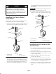
Before Operating 2 Adjusting the Height-of-Cut 3 The height-of-cut is adjustable from 1 to 4 inches (25 to 102 mm) in 1/2 inch (13 mm) increments, by adding or removing an equal number of spacers on the front and rear castor forks. The height-of-cut chart below gives the combinations of spacers to use for all height-of-cut settings.
Adjusting the Front Gage Wheel 2. Remove or add ”C” shaped spacers at the narrow portion of the spindle shaft, below the castor arm, to get the desired height-of-cut. Make sure that the thrust washers, not the spacers, contact the top and bottom of the castor arm. 1. Remove the capscrew and nut securing the gage wheel to the cutting unit brackets (Fig. 15). 2. Align the roller and spacer with the top holes in the brackets and secure them with the capscrew and nut. 3.
Checking the Lubricant in the Gear Box Operation Note: Determine the left and right sides of the machine from the normal operating position. The gear box in designed to operate on SAE 80–90 wt. gear lube. Although the gear box is shipped with lubricant from the factory, check the level before operating the cutting unit. Using the Grass Deflector 1. Position the machine and cutting unit on a level surface. Danger 2. Position the machine and cutting unit on a level surface and lower the cutting unit.
Adjusting the Tension Spring For best performance, the cutting unit bounce on uneven turf is minimal and it does not ride heavily over flat terrain. If scalping occurs or the cut is uneven from side to side, there may too much weight on the deck and weight may have to be transferred to the traction unit: i.e. increased spring tension. By contrast, if too much weight is transferred to the traction unit, the deck will bounce excessively and the cut will be uneven.
Maintenance Note: Determine the left and right sides of the machine from the normal operating position. Recommended Maintenance Schedule Maintenance Service Interval Maintenance Procedure After first 2 hours • Tighten the castor wheel nuts. After first 10 hours • Tighten the castor wheel nuts. • Torque the blade bolts. Daily • Check the blades. • Lubricate the castor arm bushings. • Lubricate the castor wheel bearings. Every 50 hours • • • • • • Every 400 hours • Change the gear box oil.
2. Position the machine and cutting unit on a level surface and lower the cutting unit. Remove the dipstick/fill plug from the top of the gear box (Fig. 23) and make sure that the lubricant is between the marks on the dipstick. If the lubricant level is low, add SAE 80–90 wt. gear lube until the level is between the marks. 1 Figure 20 Figure 23 1. Fill/check plug Separating the Cutting Unit from the Traction Unit 1.
3 2 1 1 Figure 26 1. PTO shaft Figure 24 1. Lock pin 2. Bracket 3. Spring tension assembly Danger If the engine is started and the PTO shaft is allowed to rotate, serious injury could result. 3. Position the machine on a level surface, lower the cutting unit to the floor, move the lift lever to the float position, shut the engine off, and engage the parking brake. Do not start the engine and engage the PTO lever when the PTO shaft is not connected to the gear box on the cutting unit. 4.
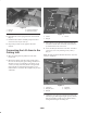
Servicing the Castor Arm Bushings lubricated, bearing wear will be minimal. However, failure to keep the bearing lubricated will cause rapid wear. A wobbly castor wheel usually indicates a worn bearing. The castor arms have bushings pressed into the top and bottom of the tube and after many hours of operation, the bushings will wear. To check the bushings, move the castor fork back and forth and from side to side.
Checking for a Bent Blade 2. Grasp the end of the blade using a rag or thickly padded glove. Remove the blade bolt, anti-scalp cup, and blade from the spindle shaft (Fig. 30). 1. Position the machine on a level surface, raise the cutting unit, engage the parking brake, put the traction pedal in neutral, the PTO lever in the Off position, shut the engine Off, remove the ignition key, and disconnect the wires from the spark plugs. Block the cutting unit to prevent it from accidentally falling. 2.
FLAT PART OF BLADE A with the anti-scalp cup and blade bolt. The blade sails must be on top of the blade. Tighten the blade bolt to 85–110 ft.-lb. (115–149 N⋅m). SAIL Correcting Cutting Unit Mismatch SAIL If one cutting blade cuts lower than the others, correct them as follows: B WEAR 1.
4. Install the pivot brackets on top of the discharge opening with the carriage bolts and nuts. The head of the carriage bolts must be on the inside of the cutting unit. MEASURE FROM BLADE TIP TO LEVEL SURFACE 5. Position the deflector mounts on the pivot brackets and secure the parts together with the capscrews, locknuts, and springs. Both locknuts must face each other. Tighten the locknuts until they are flush against the deflector pivots. Figure 34 7.
Adjusting the Cover Latches If the cutting unit covers fit loose, the latch tension may be adjusted by loosening the latch mounting screws and sliding the latches (slotted mounting holes in the cutting unit) to the proper position. Replacing the Drive Belt The blade drive belt, tensioned by the adjustable idler, is very durable. However, after many hours of use, the belt will show signs of wear.
INSPECT CUTTER OK BLADES INSPECT SPINDLE OK BOLTS INSPECT CUTTER DECK OK INSPECT GEAR BOX OK INSPECT GEAR BOX BELTS PULLEY SHAFTS 25 DULL OR BENT LOOSE LOOSE OR BROKEN LOOSE BROKEN SHARPEN OR REPLACE RETORQUE 85 TO 110 FOOT POUNDS TIGHTEN OR REPLACE TIGHTEN OR REPLACE REPLACE INSPECT PULLEY ON ENGINE OUTPUT SHAFT OK INSPECT P.T.O. SHAFT OK INSPECT P.T.O. PULLEY OK INSPECT P.T.O.
The Toro General Commercial Products Warranty A Two-Year Limited Warranty Conditions and Products Covered The Toro Company and its affiliate, Toro Warranty Company, pursuant to an agreement between them, jointly warrant your Toro Commercial Product (“Product”) to be free from defects in materials or workmanship for two years or 1500 operational hours*, whichever occurs first.