Form No. 3326-909 52 Rear Discharge Mower Groundsmaster 200 Series Model No. 30568—Serial No.
Contents Contents . . . . . . . . . . . . . . . . . . . . . . . . . . . . . . . . . . . Introduction . . . . . . . . . . . . . . . . . . . . . . . . . . . . . . . . Safety . . . . . . . . . . . . . . . . . . . . . . . . . . . . . . . . . . . . . Safe Operating Practices . . . . . . . . . . . . . . . . . . . . Toro Mower Safety . . . . . . . . . . . . . . . . . . . . . . . . Safety and Instruction Decals . . . . . . . . . . . . . . . . Specifications . . . . . . . . . . . . . . . . . . . . . . . . . . . . .
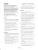
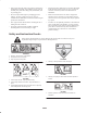
Safety – Never remove fuel cap or add fuel with engine running. Allow engine to cool before refueling. Do not smoke. This machine meets or exceeds the B71.4 1999 specifications of the American National Standards Institute, in effect at time of production. – Never refuel or drain the machine indoors. • Check that operator’s presence controls, safety switches and shields are attached and functioning properly. Do not operate unless they are functioning properly.
• The operator shall turn on flashing warning lights, if provided, whenever traveling on a public road, except where such use is prohibited by law. Operation • Know how to stop the machine quickly. • Always wear substantial shoes. Do not operate the machine while wearing sandals, tennis shoes, or sneakers. Maintenance and Storage • Disengage drives, lower the cutting units, move traction pedal to Neutral, set parking brake, stop engine and remove key and disconnect spark plug wire.
• If the engine must be running to perform a maintenance adjustment, keep hands, feet, clothing, and any parts of the body away from the cutting units, attachments, and any moving parts. • Perform only those maintenance procedures described in this manual. If major repairs are ever needed or if assistance is desired, contact an Authorized Toro Distributor. • Do not overspeed the engine by changing governor settings.
93-7818 1. Warning—read the operator’s manual for further information on torquing the blade bolt. 105–9551 1. Warning—read the operator’s manual. 2. Lower the cutting deck when going down slopes. GM 225 units need 25 kg (55 lb.) of rear weight. GM 228D and four-wheel drive units do not need any rear weight. 99–5171 93-7820 1. Remove the ignition key before performing maintenance. 2.
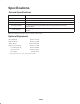
Specifications General Specifications Width of Cut 51-3/4 in. (1.314 m) Height of Cut Adjustable from 1 to 3-1/2 in. (25 to 89 mm) in 1/2 inch (13 mm) increments Blade Tip Speed Cutting Blades Pneumatic Wheels Drive System 15,764 ft./min. @ 3300 engine RPM 3 heat-treated steel blades, each 3/16 in. (4.8 mm) thick and 18 in. (457 mm) long 8 in.
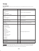
Setup Loose Parts Note: Use this chart as a checklist to ensure that all parts have been received. Without these parts, total setup cannot be completed. Description Qty. Right-hand lift arm 1 Left-hand lift arm 1 Spacer 2 Pivot pin assembly 2 Cotter pin, 5/32 in. x 1-3/4 in. 2 Rear cradle 2 Spacer 2 Capscrew, 3/8 x 2 in. 6 Flange nut, 3/8 in. 6 Carrier frame 1 Capscrew, 1/2 x 1-1/2 in.
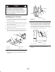
Danger If the engine is started and the PTO shaft is allowed to rotate, serious injury could result. Do not start the engine and engage the PTO lever when the PTO shaft is not connected to the gear box on the cutting unit. 1 3 3 2 Installing the Lift Arms Figure 3 1. On one side of the traction unit, loosen (do not remove) the wheel nuts securing the wheel and tire assembly to the front wheel studs. 1. Cylinder pin 2. Cylinder end 2. Jack up the machine until the front wheel is off of the floor.
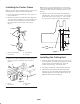
Installing the Carrier Frame Note: If the rear cradle mounting holes are not in the lift arms, use the dimensions shown in Figure 7 to locate, mark, and drill the 3 holes (13/32 in. diameter) required in each lift arm. Note: Grease the castor wheel shaft with No. 2 grease after installing and after initial operation of the machine. 4. Slide the carrier frame onto the lift arms aligning the mounting holes. Secure each side of the carrier frame to the lift arms with 3 capscrews (1/2 x 1-1/2 in.).
3. Place blocks under the cutting deck to prevent it from falling during assembly. 3 Note: The mounting brackets for the weight transfer kit must be installed in different locations depending on the cutting deck. Refer to Figure 10 for mounting location. 4 1 2 Figure 8 1. PTO shaft 2. Bolts and locknuts 3. Gear case shaft 4. Roll pin 3 2 1 4 3 Figure 10 1. 52″ side discharge deck 2. 52″ deck w/bagger 4.
7. Mount the bottom of the knee link to the deck bracket with a shoulder bolt and locknut. 8. Align the slotted holes in the spring cover (slot toward the bottom) with the mounting bracket holes. Insert the lock pin assemblies into the bracket holes and secure each to the bracket with self-tapping screws (Fig. 12). Torque the screws to 20 ft.-lb. (27 N⋅m). 4 3 2 1 8 1 9 6 REAR 5 Figure 13 7 12 1. Wide part of knee link 11 10 1 Figure 12 1. 2. 3. 4. 5. 6. 7.
hole the lowest, etc. Align the top spring end hole with the selected spring cover holes and insert the clevis pin to secure the spring inside the cover (Fig. 12). Secure the clevis pin with a hairpin cotter. Before Operating Adjusting the Height-of-Cut 10. Remove the blocks from under the cutting unit. Make the final counterbalance adjustments under actual cutting conditions; refer to Adjusting the Tension Spring, page 14.
Checking the Lubricant in the Gear Box Operation Note: Determine the left and right sides of the machine from the normal operating position. The gear box is designed to operate on SAE 80–90 wt. gear lube. Although the gear box is shipped with lubricant from the factory, check the level before operating the cutting unit. Adjusting the Tension Spring 1. Position the machine and cutting unit on a level surface.
Maintenance Note: Determine the left and right sides of the machine from the normal operating position. Greasing the Bearings and Bushings The cutting unit must be lubricated regularly. If the machine is operated under normal conditions, lubricate the castor bearings and bushings with No. 2 general purpose lithium base grease or molybdenum base grease after every 8 hours of operation or daily, whichever comes first.
Separating the Cutting Unit from the Traction Unit 1. Position the machine on a level surface, raise the cutting unit, engage the parking brake, put the traction pedal in neutral, the PTO lever in the Off position, shut the engine off, and remove the ignition key. 1 Caution The counterbalance spring is in tension when the deck is in the lowered position. 1 Figure 24 1. PTO shaft Always raise the deck before adjusting or removing the spring. Danger 2.
Servicing the Castor Wheel and Bearing 4. Insert a pin punch into the top or bottom of the mounting tube and drive the bushing out of the tube (Fig. 25). Also drive the other bushing out of the tube. Clean the inside of the mounting tube to remove any dirt. The castor wheel rotates on a high-quality roller bearing and is supported by a spanner bushing. Even after many hours of use, provided that the bearing was kept well lubricated, bearing wear will be minimal.
Checking for a Bent Blade 2. Grasp the end of the blade using a rag or thickly padded glove. Remove the blade bolt, anti-scalp cup, and blade from the spindle shaft (Fig. 28). 1. Position the machine on a level surface, raise the cutting unit, engage the parking brake, put the traction pedal in neutral, the PTO lever in the Off position, shut the engine Off, remove the ignition key, and disconnect the wires from the spark plugs. Block the cutting unit to prevent it from accidentally falling. 2.
Checking and Correcting Mismatch of Blades If one cutting blade cuts lower than the others, correct them as follows: 1. Lower the cutting unit onto a level surface, engage the parking brake, put the traction pedal in neutral, the PTO lever in the Off position, shut the engine off, remove the ignition key, and disconnect the wires from the spark plugs. Make sure that the tire pressure is equal on all tires. 2. Raise the height-of-cut to the 3-1/2 in.
Adjusting the Idler Pulley 8. Compare the measurements at various positions. All dimensions must be equal within 1/4 in. (6 mm) from any 2 adjacent blades. The difference between the dimensions of all 3 blades must not exceed 3/8 in. (10 mm). If the difference exceeds specifications, proceed to step 9. The idler pulley applies force against the belt so that power can be transmitted to the blade pulleys.
Replacing the Drive Belt The blade drive belt, tensioned by the adjustable idler, is very durable. However, after many hours of use, the belt will show signs of wear. Signs of a worn belt are: squealing when belt is rotating, blades slipping when cutting grass, frayed edges, burn marks, and cracks. Replace the belt if any of these conditions are evident. 1.
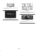
INSPECT CUTTER OK BLADES OK BOLTS DULL OR BENT LOOSE 22 RETORQUE 85 TO 110 FOOT POUNDS SHARPEN OR REPLACE INSPECT PULLEY ON ENGINE OUTPUT SHAFT INSPECT SPINDLE OK INSPECT P.T.O. SHAFT OK INSPECT CUTTER DECK OK INSPECT GEAR BOX OK INSPECT GEAR BOX BELTS PULLEY SHAFTS LOOSE OR BROKEN LOOSE BROKEN TIGHTEN OR REPLACE TIGHTEN OR REPLACE REPLACE INSPECT P.T.O. PULLEY OK INSPECT P.T.O.
The Toro General Commercial Products Warranty A Two-Year Limited Warranty Conditions and Products Covered The Toro Company and its affiliate, Toro Warranty Company, pursuant to an agreement between them, jointly warrant your 1996 or newer Toro Commercial Product (“Product”) purchased after January 1, 1997, to be free from defects in materials or workmanship for two years or 1500 operational hours*, whichever occurs first.