FORM NO. 3313-833 OPERATOR'S MANUAL MODEL: 30568 — & UP 52" REAR DISCHARGE CUTTING UNIT assure maximum safety, optimum performance, and to gain knowledge of the machine, it is essential that you or any other operator of the machine read and understand the contents of this manual before the engine is started. Pay particular attention to the instructions highlighted A by the triangular safety alert symbol, Failure to comply with the safety instructions may result in personal injury.
FOREWORD The cutting unit has advanced concepts in engineering, design and safety; and if maintained properly, will give excellent service. Since it is a high-quality product, Toto is concerned about the future use of the machine and safety of the user. Therefore, read this manual to familiarize yourself with proper set-up, operation and maintenance instructions. The major sections of the manual are: 1. Safety Instructions 2. Setup Instructions 3. Before Operating 4. Lubrication 5.
SAFETY INSTRUCTIONS 2. Do not allow children to operate the machine. Do not allow adults to operate the machine without proper instruction. 3. Remove all debris or other objects that might be picked up and thrown by the cutter blades. Keep all bystanders away from the mowing area. 4. Keep all shields and safety devices in place. If a shield, safety device or decal is malfunctioning, illegible or damaged, repair or replace it before operation is commenced.
SAFETY INSTRUCTIONS 19. Lower the cutting unit to the ground and remove key from ignition switch whenever machine is left unattended. MAINTENANCE 20. Remove key from ignition switch on all machines and disconnect high tension wire from spark plug on gasoline engines to prevent accidental starting of the engine when servicing, adjusting or storing the machine, 21, Perform only those maintenance instructions described in this manual.
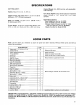
SPECIFICATIONS CUTTING UNIT: Width of Cut: 51-3/4 in. {1.315 m). Height-of-Cut: Adjustable from 1”10 {25 to 89 mm}in 1727 {13 mm) increments. Blade Tip Speed: 15,764 mindful. (80.08 m/sec.} @ 3300 engine RPM. ' Cutter Blades: Three heat treated steel blades, each 3/16 in. (4.8 mm} thick and 18 in. (457 mm} long. Castor Wheels: 8 in. (203 mm) dia. with grease able rosier bearings. Unit Drive System: PTO driven gear box transmits power through a "AA” section belt to all blade spindles.
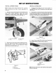
SET-UP INSTRUCTIONS INSTALL CARRIER FRAME Note: Grease castor wheel shaft with No. 2 grease after installing and after initial operation of machine. 1. Remove Lynch Pins and two thrust washers from each castor wheel assembly. Leave two thrust washers on each shaft, insert shafts into frame, install thrust washers and Lynch pins (Fig. 1} Figure 1 7. Castor wheel assembly 2 frame 3. Thrust washers 4. Lynch pin 2. Slide carrier frame onto lift arms aligning mounting holes.
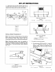
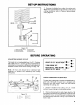
SET-UP INSTRUCTIONS 4. Install clevis pins through desired height-of-cut bracket holes and frame to secure cutting unit to frame {Fig. 5). Secure all four pins with hairpins. GM 220-D & GM 224 Figure 7 1. 52" decks 2 62* deck swaggerer 3. 627 & 72" decks Figure 5 in 3in 217200 5. 6 INSTALL WEIGHT TRANSFER KIT Note: Fully raise the cutting deck, set the parking brake, rotate the ignition key to OFF and remove it from the ignition switch.
SET-UP INSTRUCTIONS B. Grounds master 217-D and 220 — Align the bracket with the frame mounting holes. insert cap screws through the non slotted bracket holes and frame mounting holes. Install knockouts and tongue to 45-50 ft-In (Fig. 10} Figure 10 1. caseworker (2 2. Non-storied hole 3. Lockout 4 GM 220/217-D 2. Thread the top extension spring coil into the top spring end holes and the bottom extension spring coil into the bottom spring end holes {Fig. 11). 3.
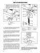
SET-UP INSTRUCTIONS Figure 13 1. Weight transfer spring 4. Deck bracket 2. Spring end plate 5. Deck frame 2 Knee jink bracket &. Flotation frame 7. Remove the blocks from under the cutting unit. Make final counterbalance adjustments under actual cutting conditions; refer to Tension Spring Adjustment, page 10.
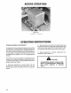
BEFORE OPERATING W Figure 15 1. Niter lag 2. Check pig OPERATING INSTRUCTIONS TENSION SPRING ADJUSTMENT For best performance, adjust spring tension so cutting unit bounce on uneven turf is minima and it does not ride heavily over fairly flat terrain. lf scalping occurs or the cut is uneven from side to side, there may be too much weight on the deck and weight may have to be transferred to the traction unit; i.e., increased spring tension.
LUBRICATION MAINTENANCE GREASE BEARINGS, BUSHINGS AND GEAR BOX The cutting unit must be lubricated regularly, If machine is operated under normal conditions, lubricate castor bearings and bushings with No. 2 general purpose lithium grease or molybdenum base grease, after every 8 hours of operation or daily, whichever comes first. All other bearings, bushings and the gear box must be lubricated after every 50 hours of operation. 1.
CUTTING UNIT MAINTENANCE A DANGER Do not start the engine and engage the SEPARATING CUTTING UNIT FROM TRACTION UNIT 1. Position machine on level surface. Raise cutting unit, engage parking brake, be sure traction pedalos in neutral position and PTO lever is in OFF position. Shut engine off and remove key from switch A CAUTION Counterbalance springs are in tension when deck is in lowered position. Always raise deck before adjusting or removing springs. 2.
CUTTING UNIT MAINTENANCE operation, the bushings will wear. To check the bushings, move castor fork back and forth and from side-to-side. i castor spindle is loose inside the bushings, bushings are worn and must be replaced. 1. Raise cutting unit and block it so it cannot fall accidentally. 2. Remove lynch pin and thrust washers from top of castor spindle. 3. Ult castor spindle out of mounting tube. Allow thrust washers to remain on bottom of spindle. 4.
CUTTING UNIT MAINTENANCE Block cutting unit to prevent it from falling accidentally. 2. Rotate blade until the ends face forward and backward (Fig. 23). Measure from inside of cutting unit to cutting edge at front of blade (Fig. 23}, and remember this dimension. Figure 23 3. Rotate opposite end of blade forward, Measure between the cutting unit and cutting edge of blade at the same position as in step 2. The difference between dimensions obtained in steps 2 and 3 must not exceed 1/8 inch {3 mm}.
CUTTING UNIT MAINTENANCE FLAT PART @ OF BLADE SAIL = wear @ BALK, SLOT FORMED Figure 25 SHARPEN AY SAH ORIGINAL ANGLE END VIEW OF BLADE Figure 26 3. Inspect cutting edges of all blades. Sharpen the cutting edges if they are dull or nicked. Sharpen only the top side of the cutting edge and maintain the original cutting angle to make sure of sharpness {Fig. 2B). The blade will remain balanced if same amount of metal is removed from both cutting edges.
CUTTING UNIT MAINTENANCE 8. Compare measurements at various positions. All dimensions must be equal within 1/4in. (6 one another. The difference between dimensions must not exceed 174 in. (6 mm). i difference exceeds 1/4 in. (6 mm), add shims between spindle housing and bottom of cutting unit, step 9, and/or move thrust washers on castor shafts, step 10. 9. Remove cap screws, flat washers, lock washers and nuts from outer spindle in the area where shims must be added.
CUTTING UNIT MAINTENANCE REPLACING DRIVE BELT The blade drive belt, pensioned by the adjustable idler, is very durable. However, after many hours of use, the bat will show signs of wear. Signs of a worn belt are: squealing when belt is rotating, blades slipping when cutting grass, frayed edges, burn marks and cracks. Replace the belt if any of these conditions are evident. 1. Lower cutting unit to the floor, engage parking brake, be sure traction pedal is in neutral and PTO lever is in OFF position.
IDENTIFICATION AND ORDERING MODEL AND SERIAL NUMBERS The cutting unit has two identification numbers: a model number and a serial number. These numbers sre stamped into a plate. The cutting unit identification plate is located just behind the right castor wheel {Fig. 34} In any correspondence concerning the cutting unit, supply the model and serial numbers to assure correct information and replacement parts are obtained.
WYY The Turn Promise A ONE YEAR LIMITED WARRANTY The costs of parts and labor are included, but the customer pays the transportation costs on walk rotary mowers with cutting unit widths of fess than 25", Commercial Products .o . . 1 Year The costs of parts and labor are included, but the customer pays the transportation costs on walk rotary mowers, trimmers and blowers. 1f you feel your TOR product is defective and wish to rely on The Toto Promise, the following procedure is recommended: 1.