
Installation Instructions

1
All Rights Reserved
Printed in the USA
2003 by The Toro Company
8111 Lyndale Avenue South
Bloomington, MN 55420-1196
Cold Start Kit
Groundsmaster
580–D
Model No. 30590
Form No. 3351–399
Installation Instructions
Danger
This kit must not be used on Groundsmaster
580–D, Model 30582–240000001.
Do not smoke when installing, maintaining, testing
or trouble shooting the cold starting system. Make
sure you are In a well ventilated area away from
heat, open flames or sparks. Wear goggles when
testing to avoid eye Injury. Starting fluid Is
extremely flammable and toxic. It can be harmful
or fatal If swallowed. Avoid contact with skin or
eyes or breathing the fumes. if fluid or fumes
enter or irritate the eyes, flush with large
quantities of water for 15 minutes and contact a
physician. Contents of canister are under
pressure. Store in a cool area. Do not incinerate,
puncture or attempt dismantle canister.
Warning
Important The Groundsmaster 580 D glow plug
circuit is designed so it can be used with the cold starting
kit. The glow plug circuit does not need to be dismantled
to use the cold starting kit. The glow plugs are energized
only when the ignition key is in the RUN position and the
kit will only inject ether during cranking.
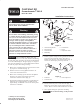
1. Mount valve assembly bracket to injector bracket with
(4) capscrews and locknuts (Fig. 1).
2. Remove fasteners securing dipstick bracket to air
cleaner base. Discard fasteners.
3. Mount valve assembly, injector bracket and dipstick
bracket to air cleaner base with (2) capscrews,
lockwashers and flat washers (Fig. 1).
4. Thread elbow fitting (left–hand dry seal threads) into
bottom of valve finger tight (Fig. 1). With wrench,
tighten fitting an additional 1 or 2 turns until it points
toward rear of machine.
TO
STARTER
TO
GROUND
1
2
4
3
5
6
Figure 1
1. Valve assembly bracket
2. Injector bracket
3. Air cleaner base
4. Elbow fitting
5. Cold start tube
6. Nozzle
7. Temperature switch
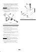
5. Remove (2) hose clamps securing intake tube between
air cleaner hose and turbo charger hose (Fig. 2).
Remove tube. Replace with cold start tube (Fig. 1)
and secure with clamps previously removed.
1
2
3
Figure 2
1. Intake tube
2. Air cleaner hose
3. Turbo charger hose
6. Thread nozzle into port on cold start tube (Fig. 1).
Make sure nozzle orifice in tube points toward air
cleaner. Mark on nozzle indicates direction of orifice.
7. Insert plastic tubing into protective sheathing.
Important Do not shorten tubing, use all provided.