
Installation Instructions


1
All Rights Reserved
Printed in the USA
2002 by The Toro Company
8111 Lyndale Avenue South
Bloomington, MN 55420-1196
Form No. 3327–491
Installation
Instructions
Model No. 30591 –220000001 & Up
Model No. 30592 –220000001 & Up
Model No. 30593 –220000001 & Up
Replacement Deck
Groundsmaster 580–D
Front Cutting Unit
If replacing a front cutting unit with a serial number
prior to 219999999, use steps 1 thru 21. If cutting unit
serial number is 220000001 or higher, proceed to step
22.
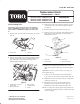
1. Remove deck covers and relieve belt tension on all belts
(Fig. 1).
1
2
Figure 1
1. Tension arm 2. Jam nuts
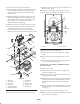
2. Remove flange head screws securing gearbox plate and
separate plate and drive motor assembly from the deck
(Fig. 2 & 3). Be careful not to bend, twist, kink or
damage flexible hydraulic lines.
1
2
3
4
5
Figure 2
1. Compression spring and
tension plate
2. Wing unit drive belt
3. Gear box plate
4. Center drive belt
5. Lift arm
3. Remove hex head screws and flange locknuts securing
each lift arm to the castor arm and separate from the
arm (Fig. 2).
4. Roll the cutting unit away from the traction unit.
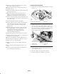
5. Remove (2) set screws and taper lock bushing securing
drive pulley to motor shaft (Fig. 3). Discard pulley,
bushing and set screws.
1
3
2
4
Figure 3
1. Drive motor
2. Gearbox plate
3. Drive pulley
4. Taper lock bushing
6. Remove (2) carriage bolts and flange nuts securing
drive motor to gearbox plate (Fig. 3). Discard gearbox
plate.
Note: Make sure three groove belt is in center pulley of
deck spindle (Fig. 4).
7. Loosely secure motor mount to deck with (4) 3/8 x
1” lg. capscrews, lockwashers and flatwashers (Fig. 4).
8. Mount drive motor to slide plate with (2) carriage bolts
and flange nuts (Fig. 4).
9. Mount drive pulley to motor shaft with taper lock
bushing, (3) screws and (3) lockwashers (Fig. 4).
Bushing to be flush with end of shaft within ±.06”.
10. Insert a compression spring and (2) spring holders onto
each side plate rod (Fig. 4). Position a spring holder into
end of each spring.