
Installation Instructions


1
All Rights Reserved
Printed in the USA
2003 by The Toro Company
8111 Lyndale Avenue South
Bloomington, MN 55420-1196
Road Kit
Groundsmaster 580–D
Model No. 30594
Form No. 3351–301
Installation Instructions
Initial Preparation
1. Unlatch, raise and secure hood with prop rod. Unlatch
and remove the left side panel.
2. Remove capscrews securing the battery tray and slide
the tray out.
3. Remove the negative (–) battery cable connections from
both batteries.
Wear safety goggles and rubber gloves when
working with batteries. Since the gases are
explosive, keep open flames and electrical spark
away from batteries. Do not smoke.
Warning
Remove Plug in Diagnostic
Panel
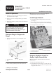
1. Remove plug from hole in front of diagnostic panel
(Fig. 1).
1
2
3
Figure 1
1. Diagnostic panel
2. Plug
3. Maim frame
2. Install a rubber grommet (Part No. 240–3) into hole.
Note: It may be necessary to enlarge hole slightly to
accommodate the wire harness connector.
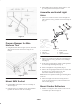
Install Light Switch
1. Locate light switch mounting location on the control
panel (Fig. 2).
2. Open control panel cover. Using a punch and hammer,
knock out plug at mounting hole location. Discard plug.
3. Install light switch in control panel.
1
2
3
Figure 2
1. Light switch mount hole
2. Control panel lift knob
3. Cup holder assembly
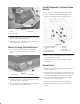
Prepare Radiator Cowl For
Amber Light Assemblies
Note: For machines without the Roll–Over Protection
(ROPS) option.
1. Remove the upper grille from cowl.
2. Using dimensions shown in figure 3, locate, mark and
drill a 17/32” dia. hole in top of cowl. Repeat procedure
on opposite side of cowl.