
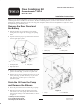
Installation Instructions

4
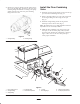
3. Connect hose “B” and the O–rings to the 90 degree
fitting on the flow combining valve and the 45 degree
fitting on the PTO manifold, as shown in figure 8.
4. Connect hose “C” and O–rings to the 45 degree fitting
on the PTO manifold to and to the T–fitting at the rear
of the pump, as shown in figure 8.
Install the Metal Tag and the
Decals
1. Affix the warning decal to one side of the metal tag
and the operating decal to the other side. Install the
metal tag to the flow combining needle with a cable
tire (Fig. 8).
2. Affix the warning decal to the center of the front frame
below the steering tower.
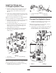
Check the Hydraulic System
1. If all three cutting units are still on the machine, make
sure to completely close the flow combining valve.
2. Make sure all hydraulic fittings are tight.
Danger
Keep body and hands away from pin hole leaks or
nozzles that elect high pressure hydraulic fluid.
Use cardboard or paper, not hands, to search for
all leaks. Highly pressurized hydraulic fluid that
is escaping can penetrate skin and cause serious
injury. If fluid is accidentally injected into the
skin, it must be surgically removed within a few
hours by a doctor familiar with this type of injury,
otherwise gangrene may occur.
3. Start the engine, lower the cutting units and engage the
deck drive/PTO switch. All cutting units should be
operating at the same speed. If the side cutting units
are not operating, disengage switch immediately and
assure that the needle valve is completely closed.
4. With the engine running and all other controls
disengaged, check for leaks around the newly installed
hydraulic parts.
5. After checking for leaks, shut the engine off.
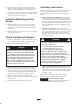
Operating Instructions
The Flow Combining Kit, by means of an in–line needle
valve between the flow combiner and the manifold,
controls the flow of oil to the front and side hydraulic
motors.
1. Using a front–mounted Implement – Attachments,
such as snowthrowers and brooms that are powered by
the front hydraulic motor, require maximum oil flow
to operate properly. To assure maximum oil flow to the
front hydraulic motor and attachment, turn the needle
valve counterclockwise until it is completely open to
combine flow.
2. Using three cutting units – Three cutting units
attached to the hydraulic motors require equal oil flow
and power so the blades operate at the same speed. To
separate flow and assure equal oil flow to all three
hydraulic motors, turn needle valve clockwise until it
is completely closed.
If the flow combining needle valve is accidentally
allowed to remain open:
• the front cutting unit blades will spin
excessively fast and be very noisy
• the side cutting units will not engage.
Failure to close the needle valve may result in
serious injury to the operator of the machine,
and/or bystanders, especially from thrown objects.
Whenever you notice the blades spinning
excessively fast, disengage the deck drive/PTO
switch immediately. Then have a qualified
mechanic close the needle valve before you
resume operating the cutting units.
Caution
3. Adjusting the Implement Drop Rate (Flow Control
Valve) – Rotate the flow control knob 1/4 turn (at a
time) counterclockwise, if front implement is dropping
too slow or 1/4 turn clockwise it front implement is
dropping too fast.
Note: Allow hydraulic oil to reach full operating
temperature before adjusting flow control valve.
Important DO NOT CLOSE VALVE
COMPLETELY! Doing so will restrict fluid flow and
prevent front implement from being lowered.