
Installation Instructions

1
All Rights Reserved
Printed in the USA
W 2005, 2006 by The Toro Company
8111 Lyndale Avenue South
Bloomington, MN 55420-1196
Air Ride Seat Suspension Kit
Groundsmaster
)
4000–D, 4100–D & 580–D
Model No. 30621
Form No. 3352–449 Rev C
Installation Instructions
Instructions for Groundsmaster 4000 series only. Refer
to page 3 for Groundsmaster 580–D installation
instructions.
1. Position the machine on a level surface, lower the
cutting unit, stop the engine, engage the parking brake
and remove the key from the ignition.
2. Disconnect the negative battery cable from the battery.
3. If the machine is currently equipped with a seat,
proceed as follows:
• Disconnect the seat switch wire from the traction
unit harness.
• Remove the fasteners securing the seat to the seat
base.
• Remove the seat from the seat base.
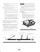
4. Remove the seat base from the machine (Fig. 1).
1
4
3
2
Figure 1
1. Seat base
2. Seat suspension
3. Seat suspension wire
4. Seat switch wire
5. Mount the air ride seat suspension to the seat base with
(4) 3/8 x 1–1/8 in. capscrews and flange nuts using the
holes shown in figure 1
6. Re–install the seat base w/ seat suspension to the
traction unit with the fasteners previously removed
(Fig. 1).
7. Mount the seat to the seat suspension per the
installation instructions included with the seat kit.
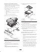
8. Remove the control panel cover (Fig. 2) to gain access
to the fuse block area.
Figure 2
1. Control panel cover
Note: Do not install the new fuse block if a third fuse
block has been previously installed.
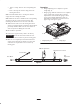
9. Mount the new fuse block below the existing fuse
block with a #10 x 3/4 in. screw and locknut (Fig. 3).
1
4
3
1
2
5
Figure 3
1. Fuse block
2. Fuse decal
3. Fuse
4. Grounding bolt
5. Grounding bolt
10. Insert the female connector from the existing fuse
block into the male connector on the new fuse block.